


 English
 Español
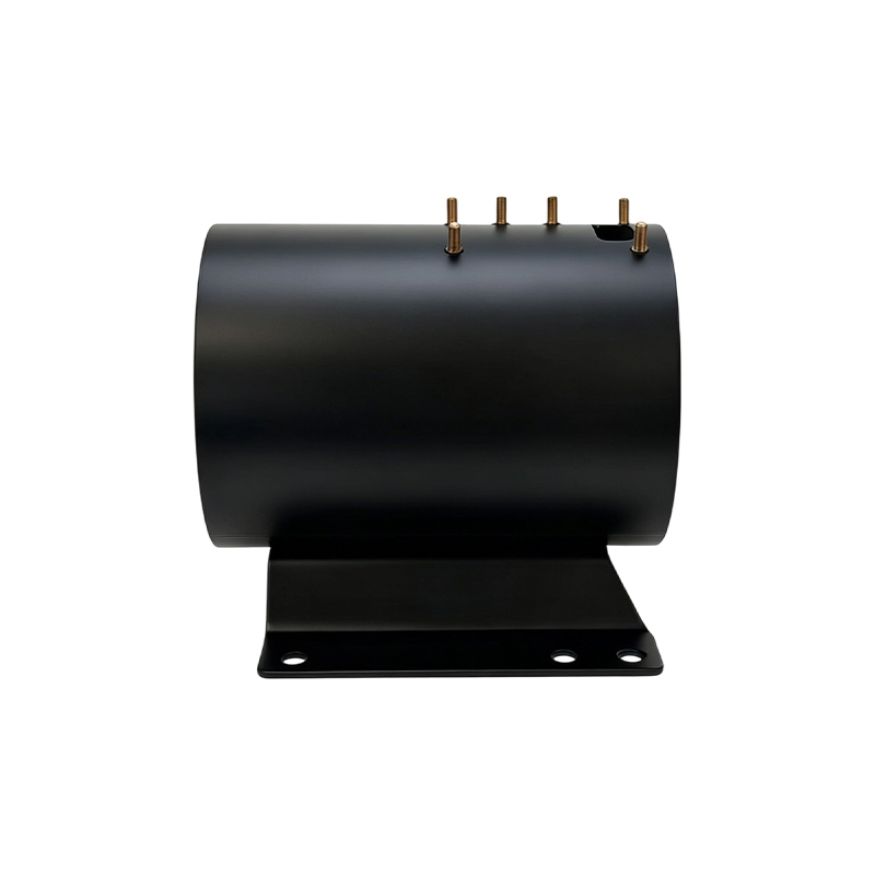
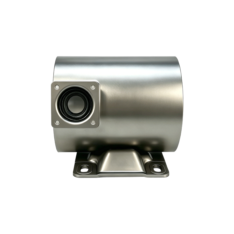
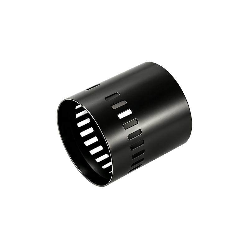
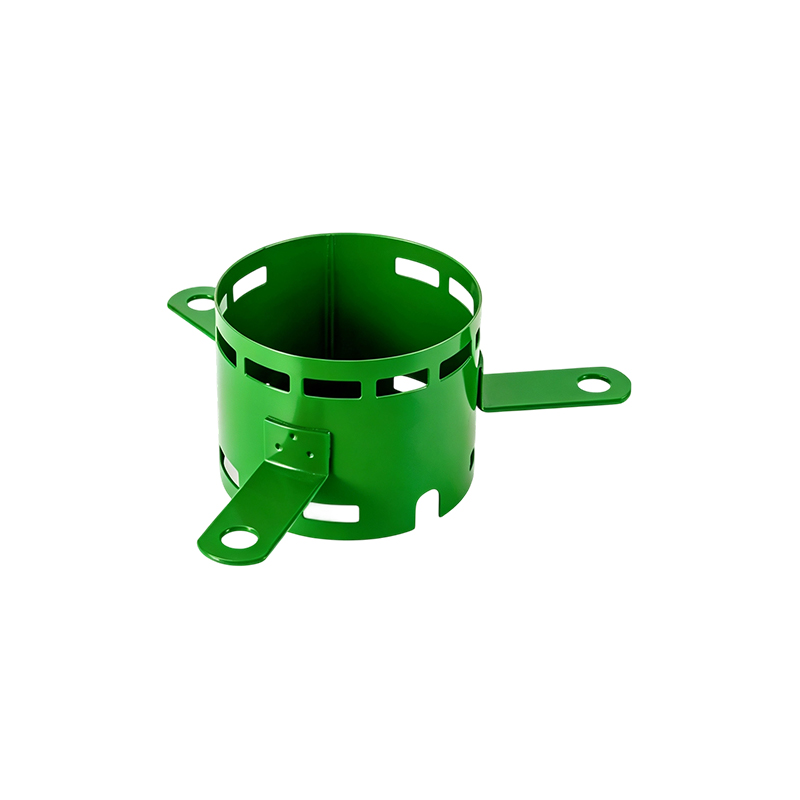
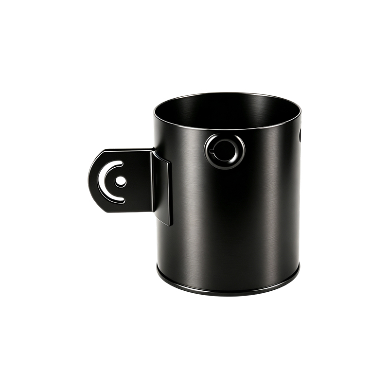
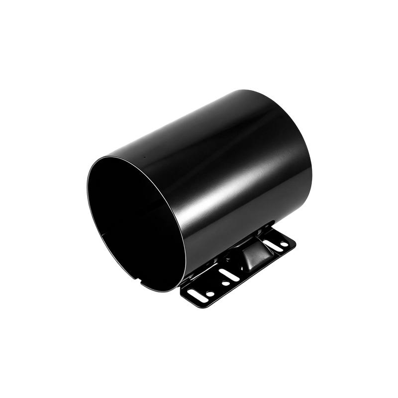
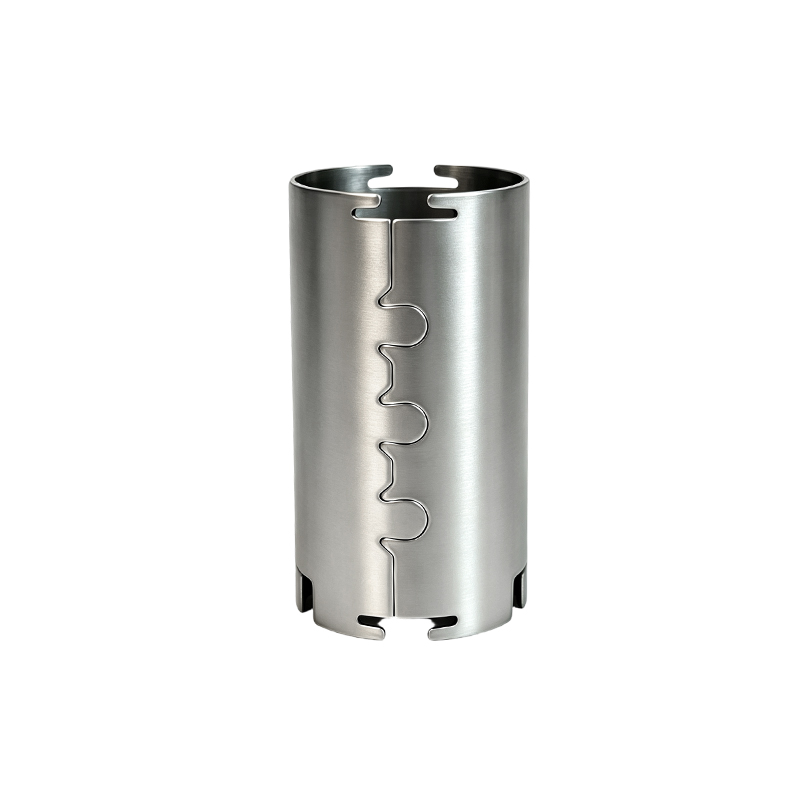
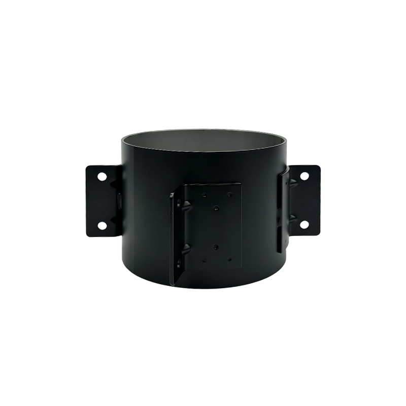
Ventilated Motor Shells
Produced by Jiangsu Yufeng Electric Co., Ltd, a motor housing manufacturer covering stamping, welding assembly, machining, and surface treatment within a single production system.
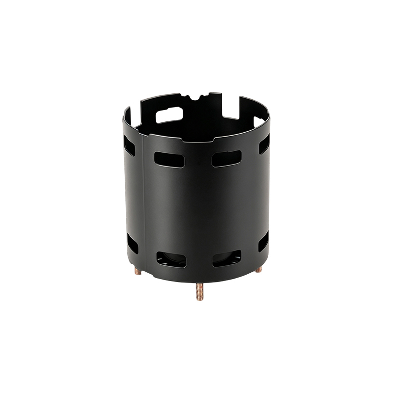
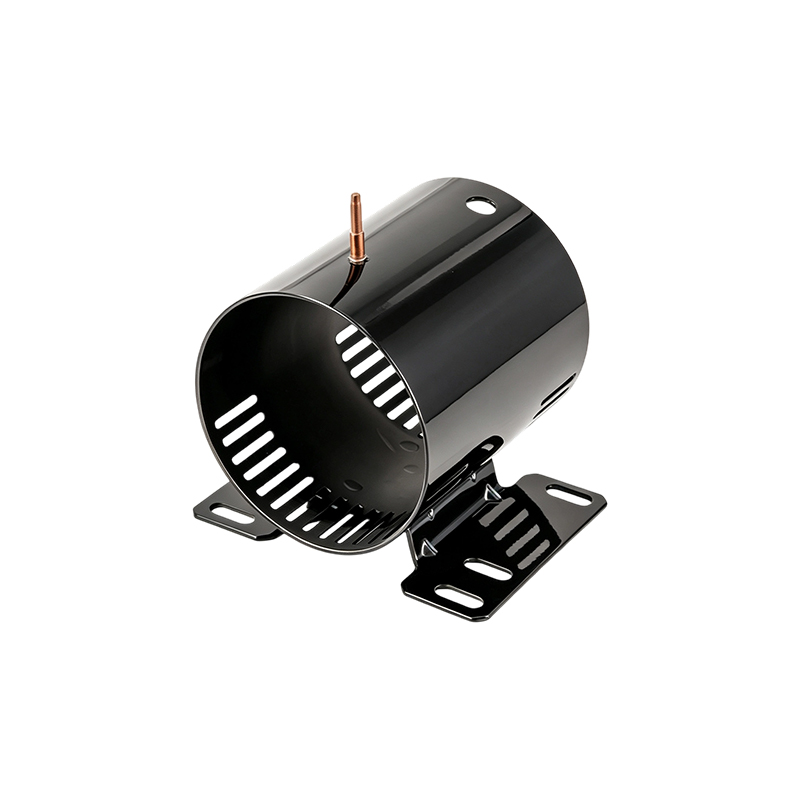
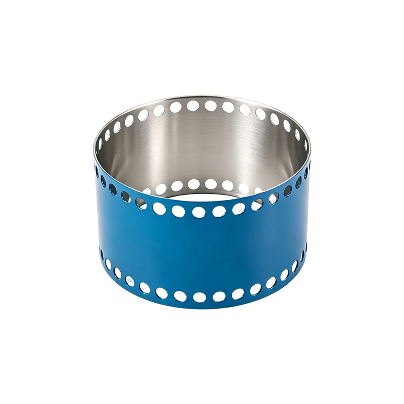
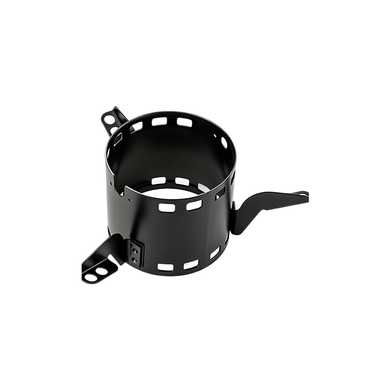
Ventilated Motor Shells from Jiangsu Yufeng Electric Co., Ltd are motor housings engineered with structured air passage openings that support heat exchange during motor operation. Each shell is formed through a stamping process, joined by welding assembly, refined by machining, and finished with surface treatment to reach the dimensional and surface requirements of household appliance motors, industrial drive motors, new energy vehicle motors, and special equipment motors. Wall sections, mounting points, and vent layouts are configured according to motor frame size and airflow requirement, supporting a range of housing diameters and lengths. Production draws on stamping lines, automated welding equipment, machining centers, and inspection instruments operating within one facility, reducing the handoff points between processing stages. Engineering staff with an average of over 20 years of experience support drawing review, tooling development, and process adjustment from prototype through mass production. With 40 years concentrated on motor housing manufacturing and an annual capacity above 5 million units, the shells are supplied in volumes suited to both development-stage orders and continuous production programs.
Core Advantages
Integrated Process Chain
Stamping, welding assembly, machining, and surface treatment are carried out in one facility, limiting transfer time and variation between stages.
Established Manufacturing Base
Forty years directed at motor housing production has built tooling, fixture, and process references applicable across housing sizes and wall configurations.
Engineering Support
An engineering team averaging over 20 years of experience supports drawing review, tooling planning, and process adjustment from sample stage to volume production.
Volume Capacity
Annual production capacity above 5 million units allows for scheduling that accommodates trial orders, phased ramp-up, and steady recurring volumes.
Inspection Coverage
Inspection instruments are applied at stamping, welding, and machining stages to track dimensional and surface condition through the production sequence.
Customer Base Across Sectors
Service to more than 50 customers spans household appliances, industrial drives, new energy vehicles, and special equipment, reflecting a range of specification requirements.
Product Features
| Material Options | Cold rolled steel, stainless steel, and aluminum sheet, selected according to load, corrosion, and weight requirement |
| Forming Method | Progressive and single station stamping for shell body, end caps, and mounting flanges |
| Assembly Method | Automated welding for seam joints, flange attachment, and bracket fixation |
| Ventilation Design | Slot, louver, or perforated opening patterns positioned according to internal airflow direction and motor frame size |
| Machining | Bore, bearing seat, and mounting hole machining to specified tolerance |
| Surface Treatment | Options including electrophoretic coating, powder coating, zinc plating, and passivation |
| Dimensional Range | Configurable diameter and length to match household appliance, industrial drive, new energy vehicle, and special equipment motor frame series |
| Wall Thickness | Configurable by sheet gauge selection to balance structural rigidity and housing weight |
| Inspection Method | Dimensional measurement, weld integrity check, and surface coating verification at defined production stages |
Application Scenarios
Household Appliances
Housings for motors used in fans, pumps, and small drive units within appliance assemblies, where compact dimensions and consistent surface finish are specified.
Industrial Drives
Housings for motors in production line drive systems, where mounting accuracy and heat exchange through ventilation openings support continuous duty operation.
New Energy Vehicles
Housings for auxiliary and drive motors within electric vehicle systems, where dimensional tolerance and material selection are matched to vehicle-grade requirements.
Special Equipment
Housings for motors used in equipment with defined operating environments, where custom mounting configurations and surface treatment are specified per project.
Manufacturing Process
Steel Processing
Sheet material is selected, cut, and prepared according to housing specification.
Stamping
Shell body, end caps, and flange components are formed on stamping lines.
Welding Assembly
Automated welding equipment joins formed components into the assembled housing structure.
Machining
Bearing seats, bores, and mounting features are machined to specified tolerance.
Surface Treatment
Coating or plating is applied according to the specified corrosion resistance and appearance requirement.
Inspection and Delivery
Inspection instruments verify dimensional and surface condition prior to packaging and shipment.
Customization and OEM Support
Shell dimensions, ventilation opening layout, mounting configuration, material, and surface treatment can be configured against a customer drawing or sample. Development support includes drawing review, tooling planning, and sample production prior to mass production release, drawing on an engineering team averaging over 20 years of experience in motor housing structure.
- Drawing-based and sample-based development for new housing designs
- Tooling development for shell body, end cap, and flange stamping
- Configurable ventilation opening pattern for specific airflow requirement
- OEM packaging and labeling arrangement available on request
Frequently Asked Questions
What dimensional range can the shells be produced in
Diameter and length are configured according to the motor frame series specified by the customer, supporting sizes used across household appliance, industrial drive, new energy vehicle, and special equipment motors.
Can ventilation opening patterns be adjusted for a specific application
Slot, louver, and perforated opening patterns are positioned according to the internal airflow direction and cooling requirement of the motor, based on the customer drawing or sample provided.
What surface treatment options are available
Electrophoretic coating, powder coating, zinc plating, and passivation are available, selected according to the operating environment and corrosion resistance requirement of the application.
Is sample production available before a mass production order
Sample production is available following drawing review and tooling confirmation, allowing dimensional and functional verification prior to mass production release.
What inspection is applied during production
Dimensional measurement, weld integrity check, and surface coating verification are applied at stamping, welding, and machining stages using inspection instruments within the facility.
What order volumes can be supported
Annual production capacity above 5 million units supports trial orders, phased ramp-up volumes, and continuous recurring production schedules within the same facility.
Ordering Considerations
- Provide a drawing or sample specifying dimension, mounting configuration, and ventilation opening layout for accurate quotation
- Specify the operating environment to determine the appropriate surface treatment option
- Confirm target motor frame series and duty condition to align wall thickness and material selection
- Indicate expected order volume and delivery schedule to align tooling and production planning
- Request sample production where a new housing design requires functional verification before mass production
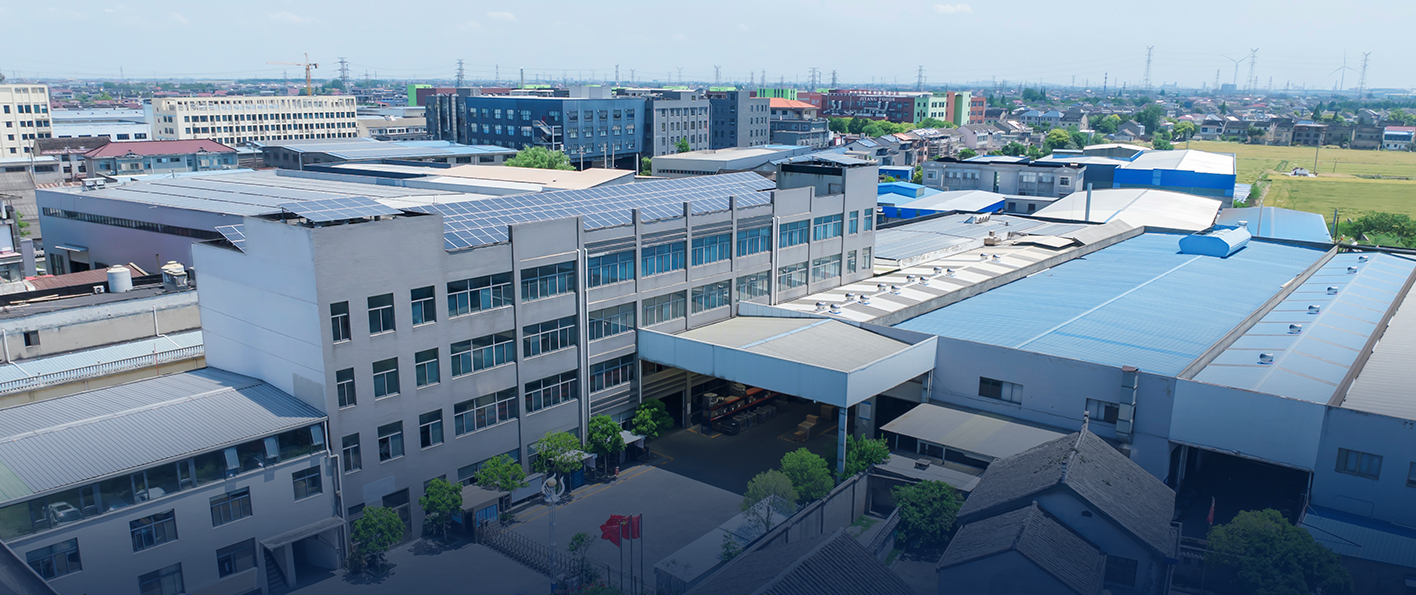
Manufacturing Solutions
We offer full-process manufacturing capabilities from steel processing to finished product delivery, supported by stamping lines, automated welding equipment, machining facilities, and inspection instruments. Backed by an engineering team with an average of over 20 years of experience, we provide technical support from development to mass production.
With 40 years of focus on motor housing manufacturing, we have served more than 50 customers and achieved an annual production capacity of over 5 million units. Guided by quality, efficiency, and fast response, we are committed to delivering high-precision and high-reliability motor housing solutions.



