


 English
 Español
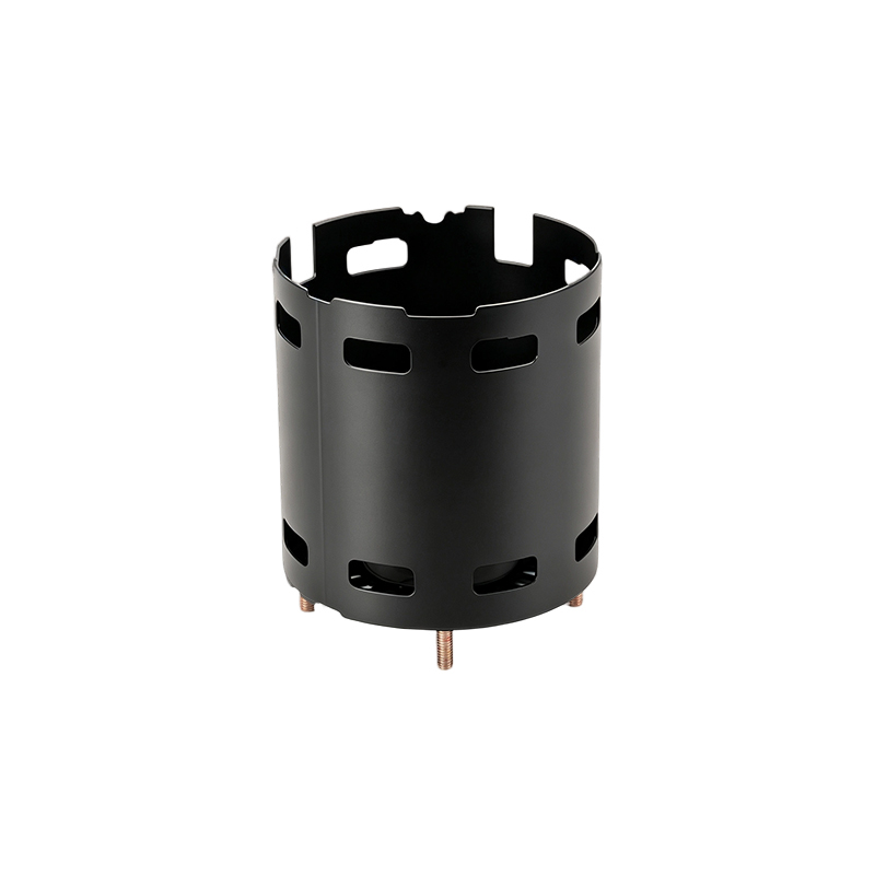
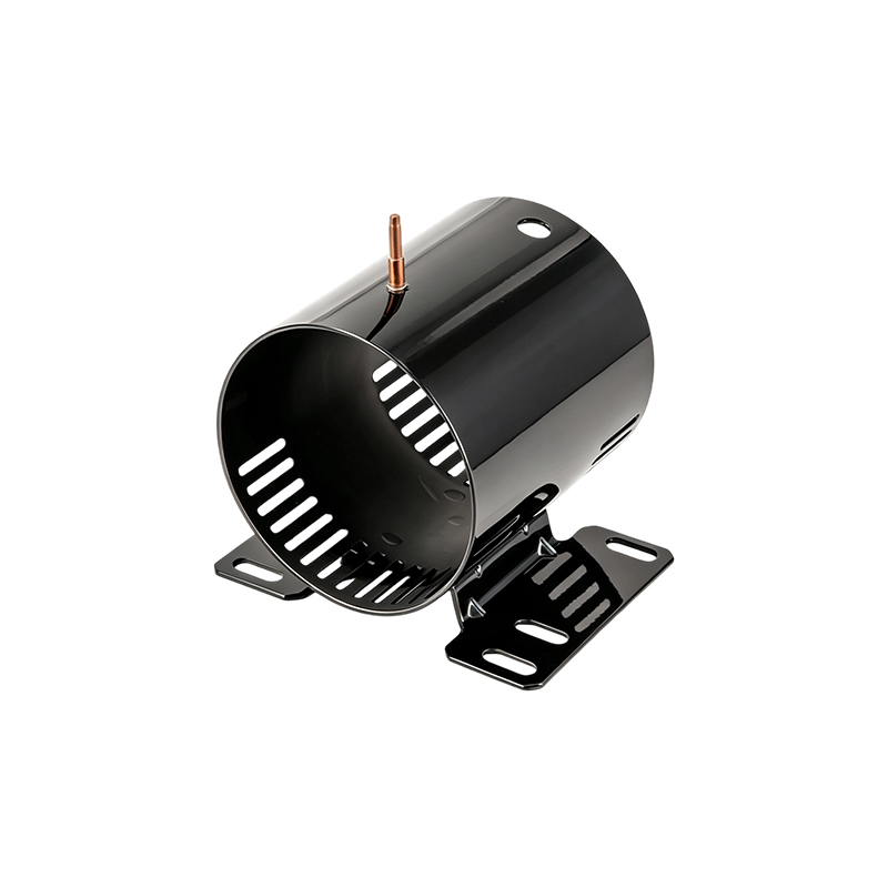
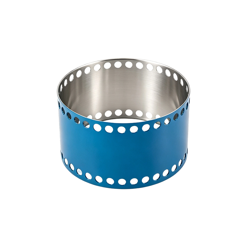
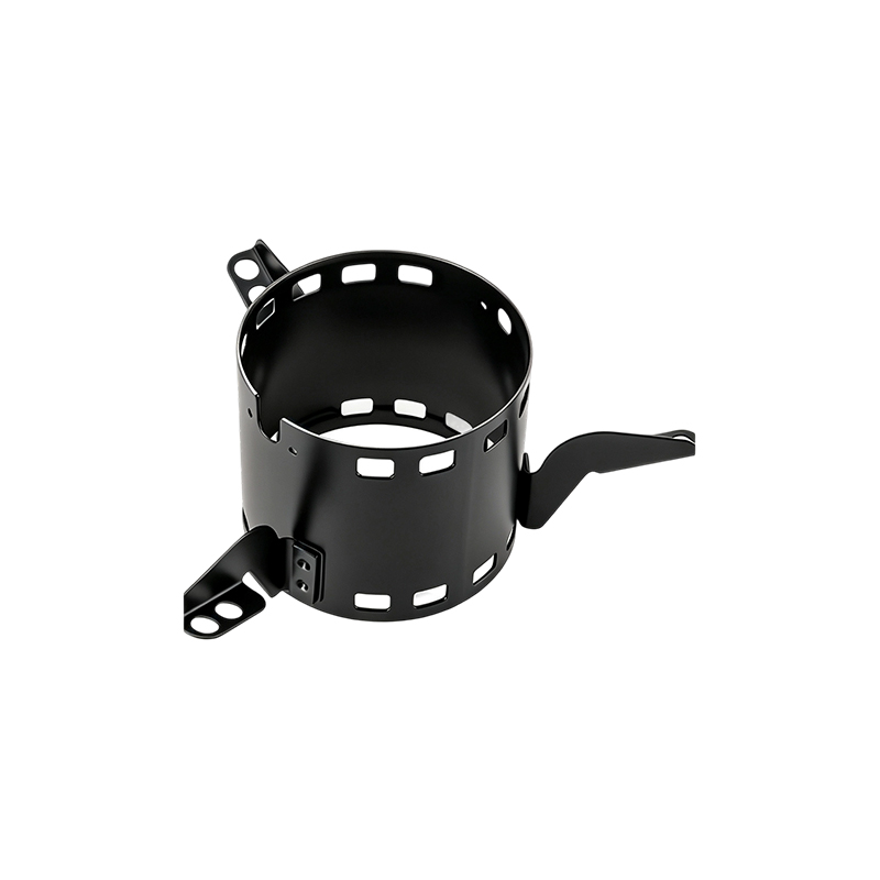
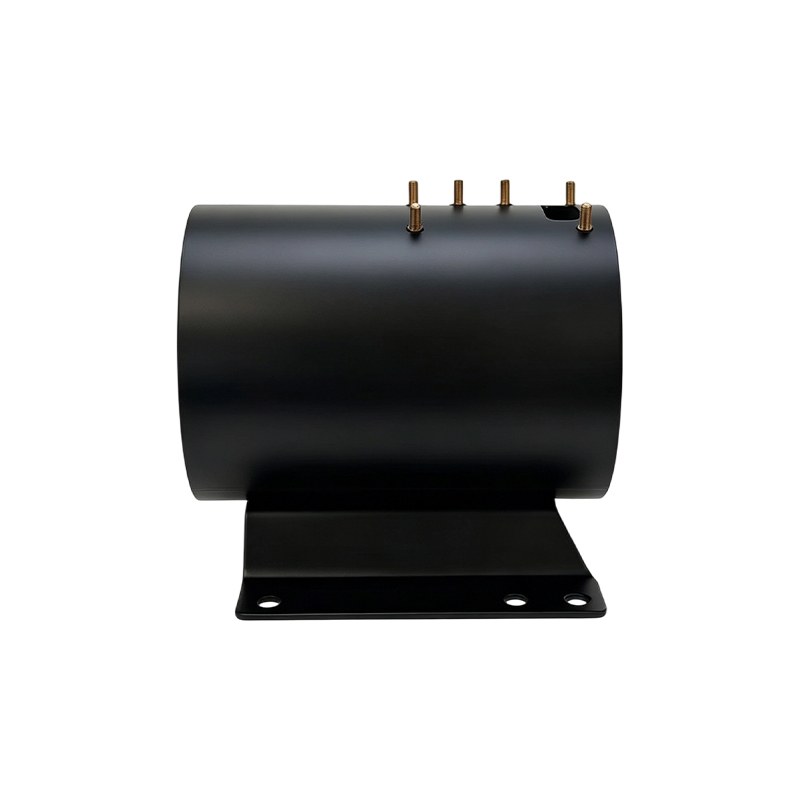
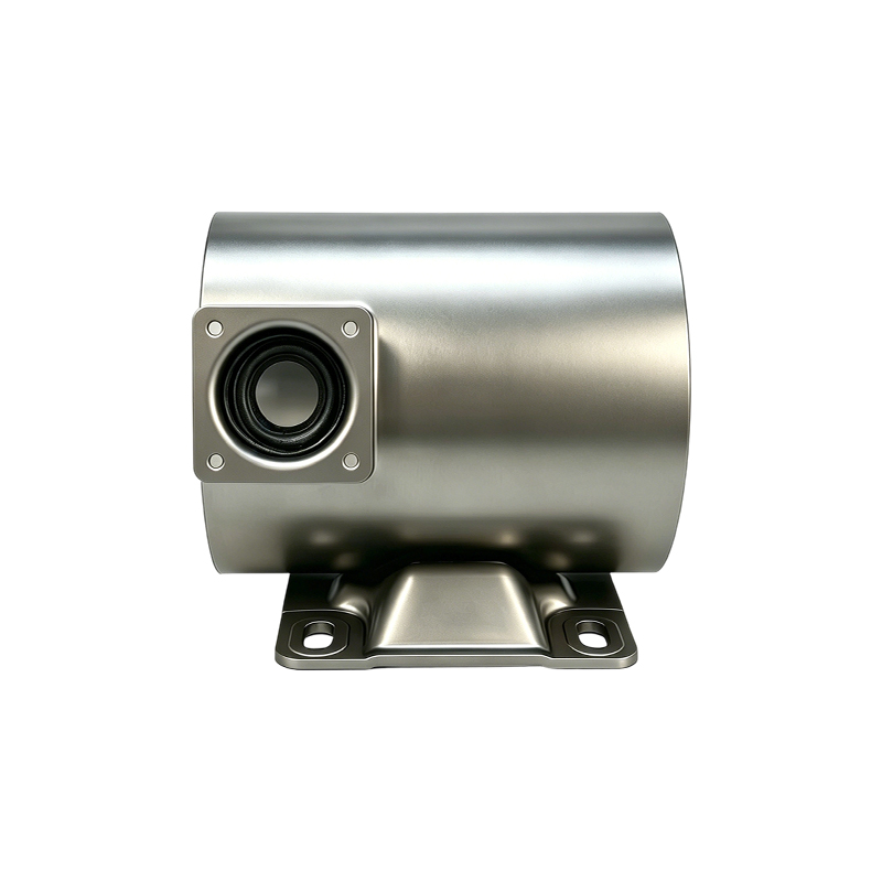
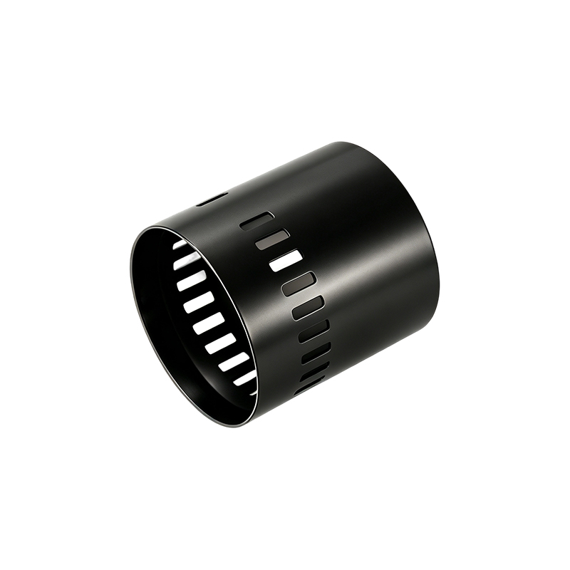
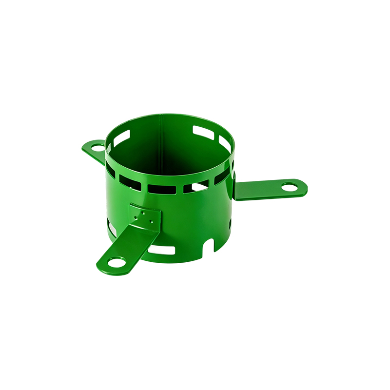
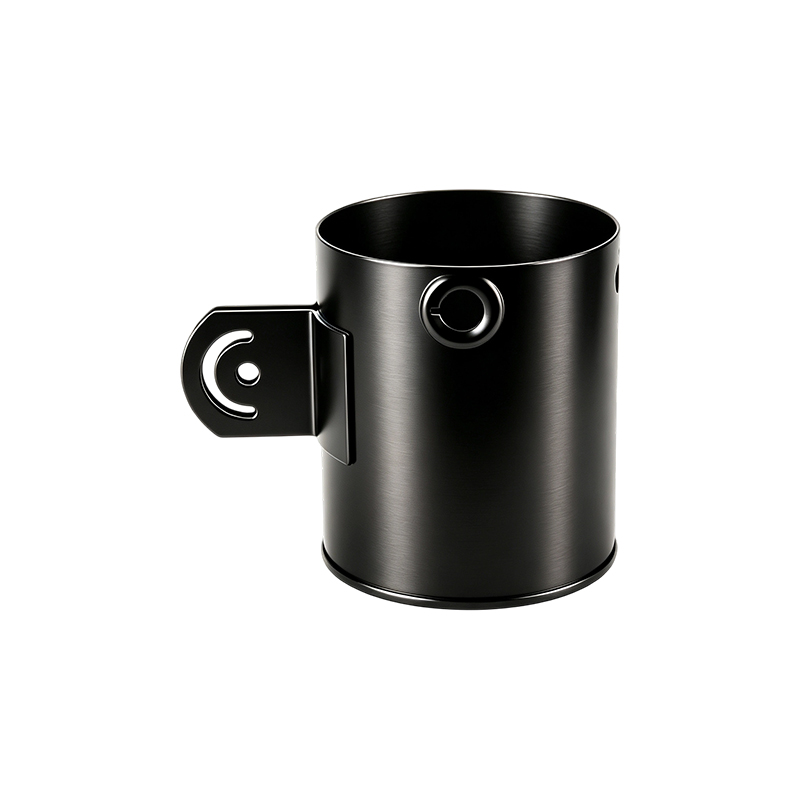
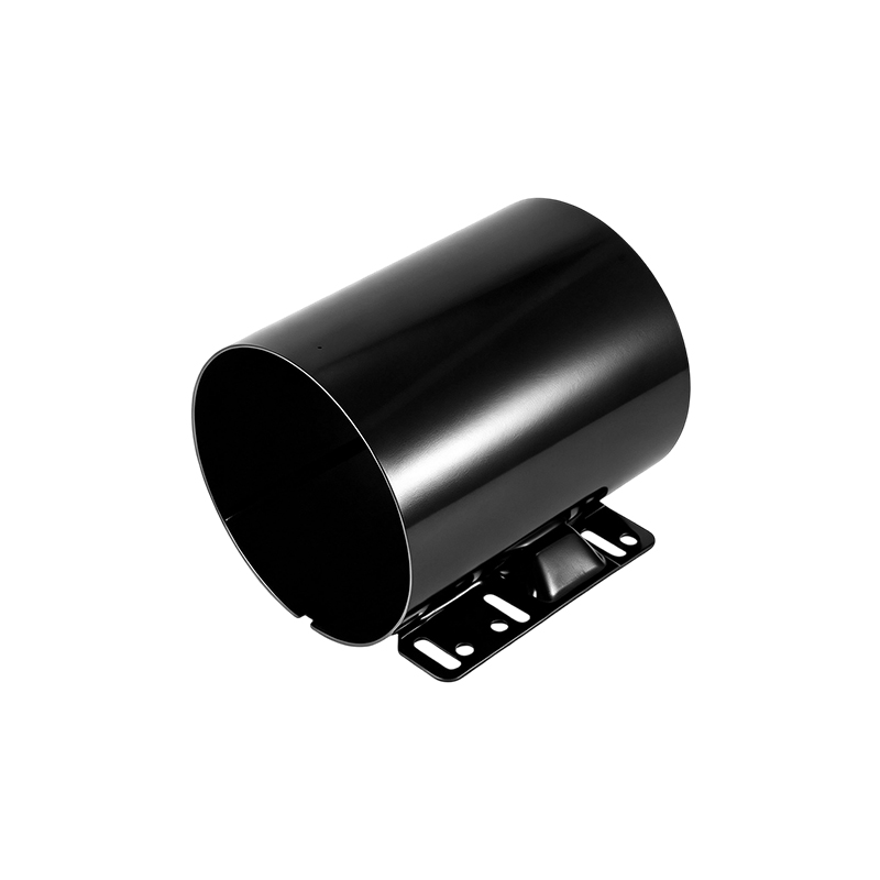
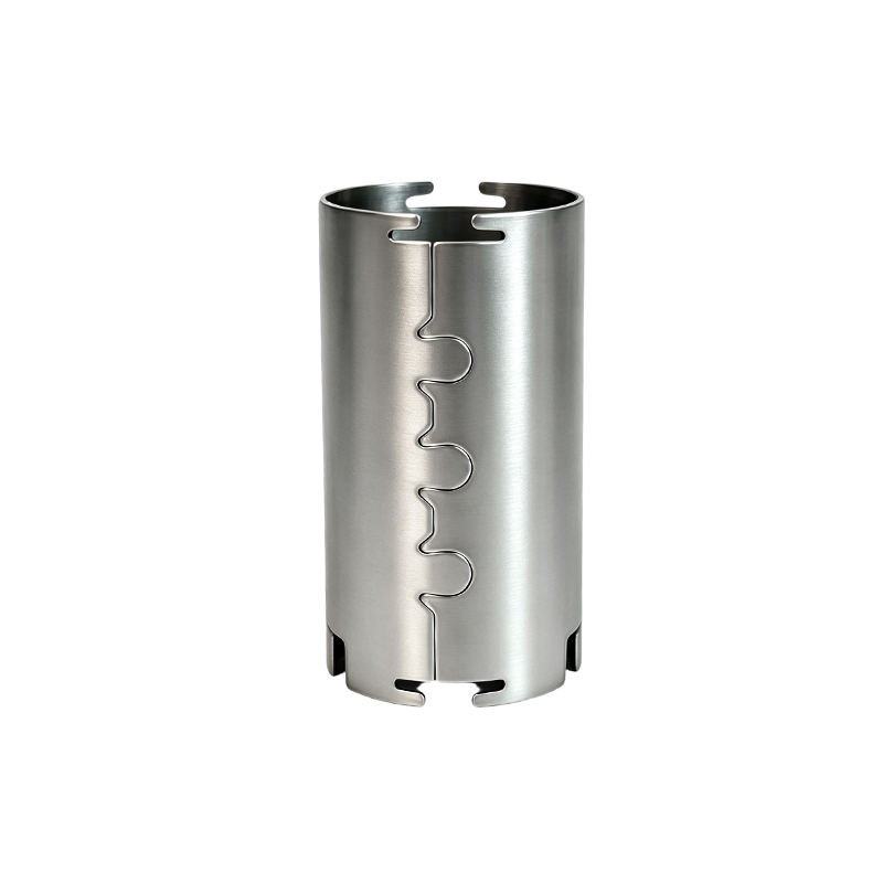
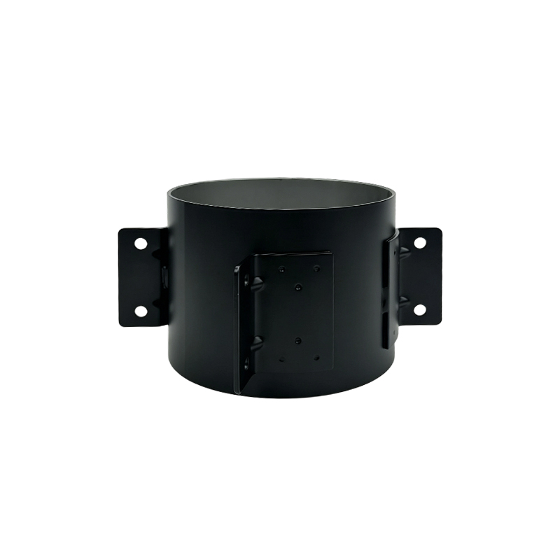
Vibration-Resistant Servo Motor Shells
Dynamic Load EnclosureA servo motor shell works under conditions that a standard motor housing does not face. Servo motors accelerate and decelerate at high rates, reverse direction frequently, and are often mounted directly on moving machine axes, so the shell absorbs dynamic loads that change direction many times per cycle. Under those conditions, stiffness, joint integrity, and bore concentricity determine whether the rotor maintains its air gap or begins to rub.
Jiangsu Yufeng Electric Co., Ltd. produces vibration-resistant servo motor shells through integrated stamping, automated welding, precision machining, and in-house electrophoretic coating and powder coating. Bore and mounting features are machined after welding, so concentricity reflects the joined shell rather than the pre-weld component. Key dimensions are verified with custom gauges and online inspection equipment.
Manufacturing Capability
Where Vibration Loads Act On A Servo Shell
Repeated Direction Reversal
Servo axes reverse direction frequently, so the shell sees cyclic loading rather than steady torque. Fasteners, joint faces, and mounting interfaces are the first points where loosening or fretting appears.
High Acceleration Torque
High acceleration rates transmit torque spikes into the shell body. Wall section and weld quality determine whether the shell resists deformation or begins to ovalize over time.
Direct Machine Mounting
Servo motors are often mounted directly on moving slides and gantries, so machine vibration passes into the shell rather than being isolated by a base frame.
Thermal Cycling
Frequent acceleration cycles raise and lower motor temperature. Repeated expansion and contraction change joint preload and can affect bore roundness if the shell is not dimensionally stable.
Bearing Alignment
Vibration transfers through the shell into bearing seats. If bore concentricity drifts, bearing preload changes and vibration increases, which accelerates wear.
Resonance Sensitivity
Stiffness and mass distribution influence the natural frequency of the assembly. A shell that is too compliant can amplify vibration near the servo operating range.
Product Specifications
| Base Material | Steel, stainless steel, and other specified metals selected for servo dynamic load and environment |
| Shell Construction | Welded body with machined bore, end faces, and mounting features |
| Bore Machining | Internal bore and end face machined after welding for concentricity and squareness |
| Mounting Interfaces | Flange and mounting features machined to drawing requirements, with position checked against assembly |
| Welding | Automated welding for repeatable seam geometry and consistent joint strength |
| Forming | Continuous stamping with material utilization above 92 percent |
| Surface Treatment | Electrophoretic coating and powder coating applied on in-house lines |
| Inspection | Custom gauges and online inspection equipment on key dimensions |
| Traceability | Batch traceable to raw material, machine, and operator |
| Quality System | ISO 9001:2015; IATF 16949 aligned process control for automotive customers |
| Customization | Bore diameter, wall section, flange pattern, mounting features, and coating adapted to servo design |
Manufacturing Steps That Address Vibration
-
Forming With Controlled Wall Section
Continuous stamping keeps wall thickness uniform around the circumference. A uniform section distributes dynamic load evenly and reduces the chance of local deformation under repeated torque reversal.
-
Automated Welding With Managed Heat Input
Automated welding produces repeatable seam geometry and consistent heat input. This limits distortion in the shell body so that bore roundness remains predictable after joining.
-
Post-Weld Bore Machining
The internal bore and end faces are machined after welding, not before. Concentricity and squareness therefore reflect the assembled shell, which supports bearing alignment and rotor air gap control.
-
Mounting Interface Machining
Flange faces, bolt patterns, and mounting features are machined to drawing requirements, with position verified so the shell mounts without introducing preload into the bearing system.
-
Coating With Adhesion Control
Electrophoretic coating and powder coating are applied on in-house lines. Coating thickness and adhesion are controlled so the surface resists chipping and corrosion under continuous machine vibration.
-
Inspection And Traceability
Key dimensions are monitored with custom gauges and online inspection equipment. Each batch traces back to raw material lots, machines, and operators, supporting fast corrective action when a deviation appears.
Application Scenarios
CNC Machine Axes
Servo shells for linear and rotary axes where frequent reversal and high acceleration place cyclic load on the housing.
Robotics And Manipulators
Shells for articulated robot joints that see repeated acceleration, deceleration, and direction changes throughout the work cycle.
Packaging Machinery
Servo housings for high-cycle indexing, filling, and sealing equipment where vibration accumulates over continuous operation.
Semiconductor Handling Equipment
Shells for precision positioning stages where bore concentricity and low vibration support accurate motion control.
Automated Assembly Lines
Servo shells for pick-and-place, pressing, and fastening stations that run repeated high-acceleration cycles.
Textile And Printing Machinery
Housings for servo-driven rollers and print heads exposed to continuous vibration and frequent speed changes.
Frequently Asked Questions
A standard motor housing mainly carries steady torque and static mounting load. A servo shell operates under rapid acceleration, frequent direction reversal, and direct machine mounting, so stiffness, joint integrity, and bore concentricity have a direct effect on rotor air gap and bearing alignment.
The internal bore and end faces are machined after welding, so concentricity and squareness reflect the joined shell. Key dimensions are checked with custom gauges and online inspection equipment to keep bearing alignment within specification across batches.
Electrophoretic coating and powder coating are applied on in-house lines. Selection considers the machine environment, coolant or lubricant exposure, and the coating adhesion needed under continuous vibration.
Yes. Bore diameter, wall section, flange pattern, mounting features, and coating can be adapted to the servo design. Changes are handled through in-house tooling design and process parameter optimization.
Standard non-standard custom samples can be delivered within 3 to 10 working days. Complex custom projects can complete first-article samples within 15 days.
Product drawings or detailed specifications, including bore diameter, wall section, flange and mounting requirements, material, surface treatment, estimated annual demand or quantity per batch, and any special technical requirements. Quotations are typically provided within 2 to 3 working days after confirmation.
Yes. Multi-variety and small-batch manufacturing is supported, covering development trials, small-to-medium volume orders, and flexible multi-batch scheduling.
Selection Notes
Dynamic Load Profile
Define acceleration rate, reversal frequency, and torque profile so wall section and joint detail match the actual duty cycle.
Bore And Bearing Fit
Specify bore diameter, concentricity, and bearing seat tolerance against the rotor and bearing arrangement.
Mounting Interface
Confirm flange geometry, bolt pattern, and pilot dimensions so the shell mounts without introducing preload into the bearing system.
Stiffness And Mass
Review wall section and material selection against the natural frequency and stiffness requirements of the machine axis.
Coating Under Vibration
Confirm coating type and adhesion requirements, since continuous vibration is more demanding on coating integrity than static service.
Traceability Scope
Define batch traceability requirements for raw materials, production processes, and finished product inspection records.
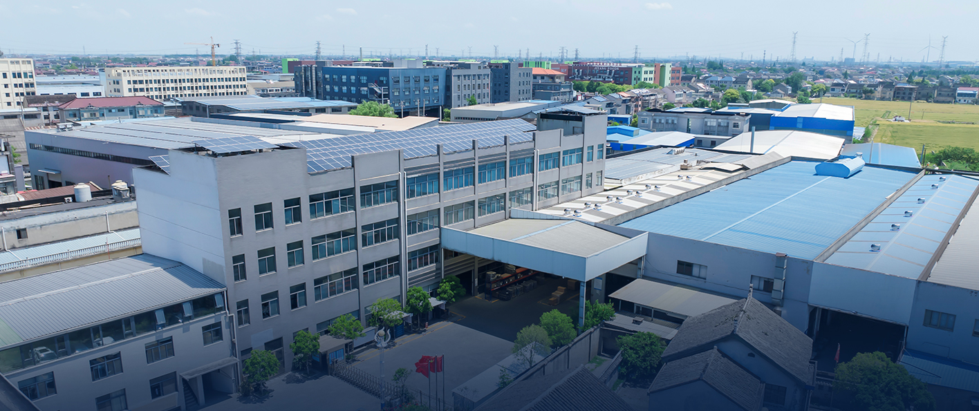
Manufacturing Solutions
We offer full-process manufacturing capabilities from steel processing to finished product delivery, supported by stamping lines, automated welding equipment, machining facilities, and inspection instruments. Backed by an engineering team with an average of over 20 years of experience, we provide technical support from development to mass production.
With 40 years of focus on motor housing manufacturing, we have served more than 50 customers and achieved an annual production capacity of over 5 million units. Guided by quality, efficiency, and fast response, we are committed to delivering high-precision and high-reliability motor housing solutions.



