


 English
 Español
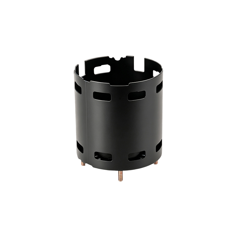
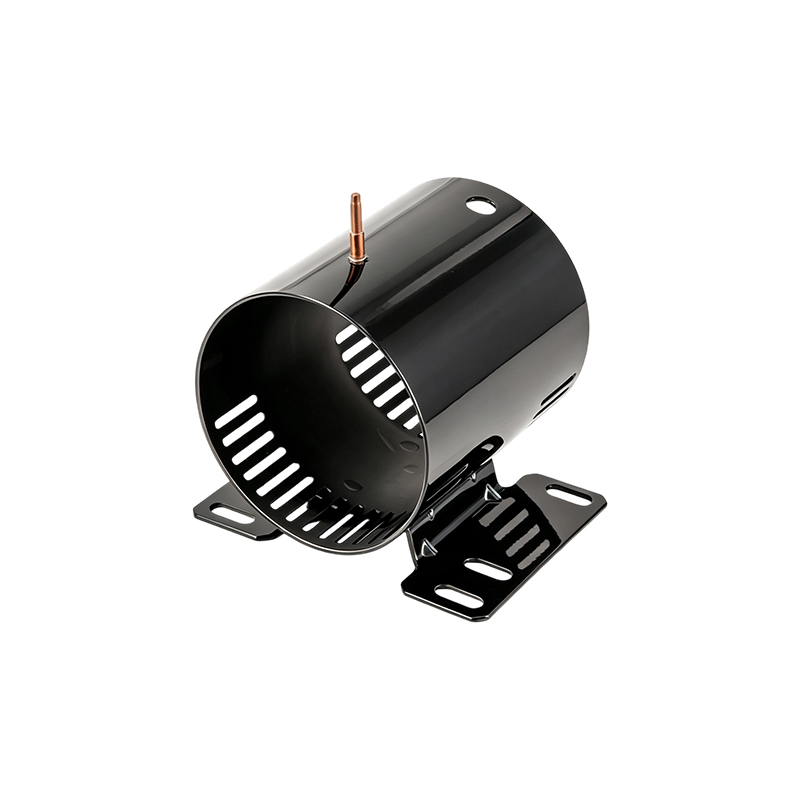
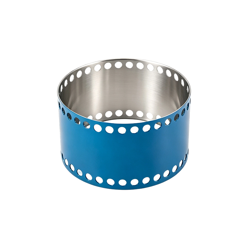
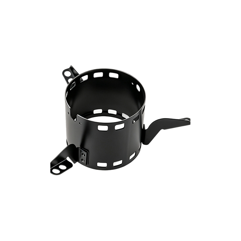
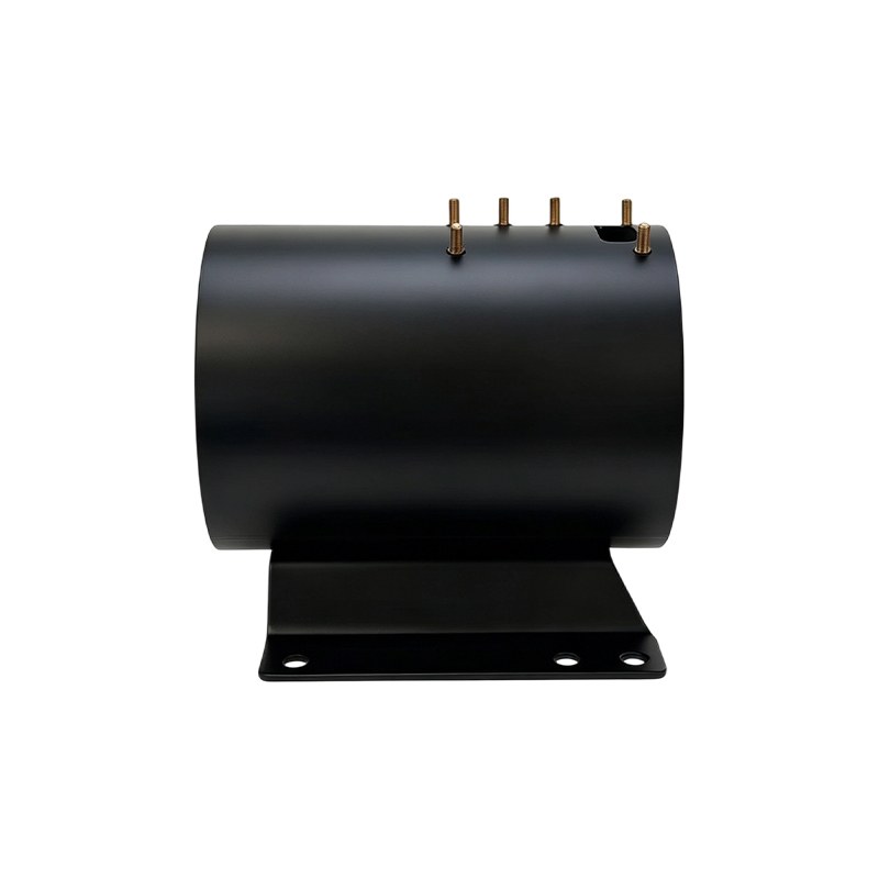
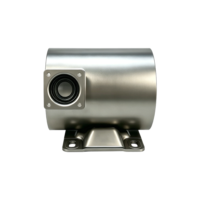
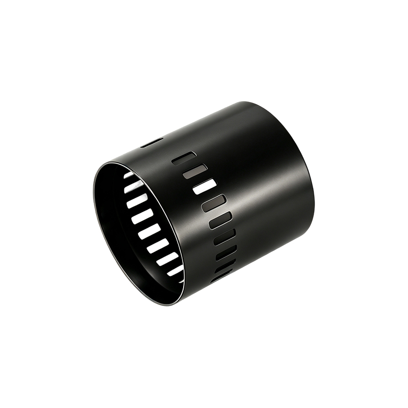
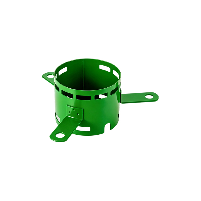
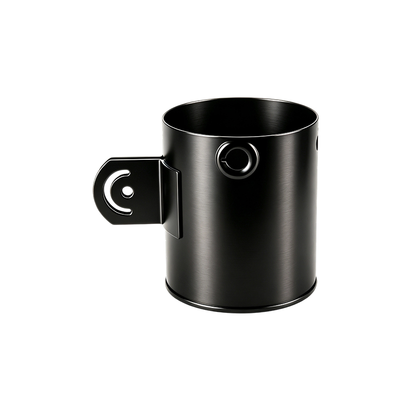
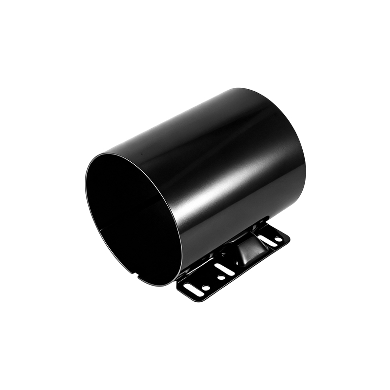
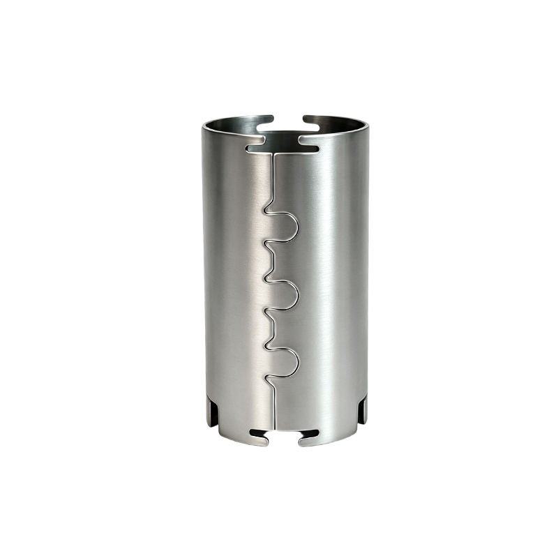
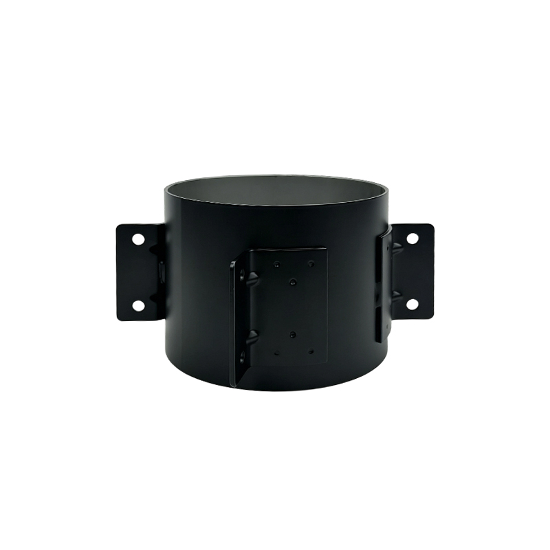
A brushless DC motor outer cover closes the motor at the shaft end and the rear end while carrying the bearing seat, the rotor position sensor mounting, and the connector or cable exit. Because BLDC motors use electronic commutation instead of brushes, the cover must keep dust, moisture, and stray metal particles out of the rotor gap and away from the sensor area, since contamination there directly affects commutation timing.
Jiangsu Yufeng Electric Co., Ltd. produces these covers with continuous stamping at material utilization above 92 percent, automated welding for repeatable seams, and precision machining on bearing seats and mating faces. Electrophoretic coating and powder coating are applied on in-house lines.
Cover Functions In A BLDC Motor
Bearing Seat Support
The cover carries the bearing seat at the shaft end. Bore diameter and concentricity determine whether the rotor stays centered and whether the air gap remains uniform during operation.
Sensor Mounting Reference
Hall sensor or encoder mounting features are located on or near the cover. Position accuracy relative to the rotor affects commutation timing and torque ripple.
Contamination Barrier
The cover closes the motor against dust, moisture, and metal particles. Joint detail and sealing surfaces determine how much contamination reaches the rotor gap and sensor area.
Thermal Path
The cover contributes to heat removal from the bearing and end winding area. Material section and contact between cover and stator influence how heat leaves the motor.
Cable And Connector Interface
Connector openings and cable exit features are formed or machined into the cover. Position and edge condition affect assembly and sealing of the cable entry.
Mounting Interface
Flange and bolt patterns on the cover connect the motor to the driven equipment. Position accuracy supports alignment between motor shaft and load.
Product Specifications
| Base Material | Steel, stainless steel, and other specified metals selected for the motor environment and load |
| Cover Construction | Formed and welded body with machined bearing seat, mating face, and mounting features |
| Bearing Seat | Machined after welding for bore diameter and concentricity |
| Sensor Mounting Area | Mounting features formed or machined to drawing requirements for position accuracy |
| Connector And Cable Exit | Openings formed or machined with edge condition suitable for sealing and assembly |
| Welding | Automated welding for repeatable seam geometry and consistent joint quality |
| Forming | Continuous stamping with material utilization above 92 percent |
| Surface Treatment | Electrophoretic coating and powder coating applied on in-house lines |
| Inspection | Custom gauges and online inspection equipment on key dimensions |
| Traceability | Batch traceable to raw material, machine, and operator |
| Quality System | ISO 9001:2015; IATF 16949 aligned process control for automotive customers |
| Customization | Cover geometry, bearing seat, sensor mounting, connector opening, and coating adapted to motor design |
Manufacturing Capabilities Applied To Covers
Continuous Stamping
Cover bodies are formed through continuous stamping with material utilization above 92 percent. Uniform wall thickness and consistent blank quality support stable downstream welding and machining.
Automated Welding
Automated welding equipment produces repeatable seam geometry on cover bodies. Weld quality is inspected before coating, supporting structural integrity and limiting paths for contamination ingress.
Post-Weld Machining
Bearing seats, mating faces, and mounting features are machined after joining. Concentricity and squareness therefore reflect the assembled cover rather than the pre-weld component.
In-House Coating
Electrophoretic coating and powder coating run on internal lines, keeping thickness, adhesion, and curing under direct process control and supporting consistent corrosion performance across batches.
Engineering Support
An engineering team with an average of over 20 years of experience supports synchronous product development, in-house tooling design, and process parameter optimization before tooling is cut.
Batch Traceability
Each batch traces back to raw material lots, production machines, and operators. Deviations can be located quickly and closed through corrective action.
Application Scenarios
HVAC And Fan Motors
Covers for BLDC fan and blower motors where dust resistance and bearing alignment affect noise and service life.
Pump Drives
Outer covers for BLDC pump motors exposed to moisture, where joint detail and coating limit water ingress.
Home Appliances
Covers for washing machine, dishwasher, and range hood motors where compact geometry and sensor position matter.
Automotive Auxiliary Drives
Covers for BLDC auxiliary motors in thermal management and actuator systems, with process control aligned to IATF 16949.
Power Tools
Outer covers for compact BLDC tool motors where dust resistance and bearing seat accuracy affect runout.
Medical And Laboratory Equipment
Covers for BLDC motors in pumps and positioning units where low vibration and clean operation are required.
Ventilation Equipment
Covers for inline and duct fan motors where connector position and cover geometry affect installation.
Industrial Automation
Covers for BLDC motors in conveyors and handling units that run continuous duty cycles.
Frequently Asked Questions
The cover closes the motor at the shaft and rear ends, carries the bearing seat, provides a mounting reference for the rotor position sensor, and protects the rotor gap and sensor area from dust, moisture, and metal particles. Because BLDC motors use electronic commutation, contamination near the sensor directly affects commutation timing.
Bearing seats and mating faces are machined after welding, so concentricity and squareness reflect the assembled cover. Key dimensions are checked with custom gauges and online inspection equipment as part of process control.
Electrophoretic coating and powder coating are both applied on in-house lines. Selection depends on the motor environment, moisture exposure, and the mechanical conditions the cover meets during assembly and service.
Yes. Cover geometry, bearing seat, sensor mounting features, connector opening, and coating can be adapted to the motor design. Changes are handled through in-house tooling design and process parameter optimization.
Standard non-standard custom samples can be delivered within 3 to 10 working days. Complex custom projects can complete first-article samples within 15 days.
Product drawings or detailed specifications, including bearing seat dimensions, sensor mounting requirements, connector opening, material, surface treatment, estimated annual demand or quantity per batch, and any special technical requirements. Quotations are typically provided within 2 to 3 working days after confirmation.
Yes. Multi-variety and small-batch manufacturing is supported, covering development trials, small-to-medium volume orders, and flexible multi-batch scheduling.
Selection Notes
Bearing Seat Tolerance
Specify bore diameter, concentricity, and bearing seat tolerance against the rotor and bearing arrangement, since these affect air gap uniformity.
Sensor Mounting Accuracy
Define the position tolerance of Hall sensor or encoder mounting features relative to the rotor, since this affects commutation timing and torque ripple.
Contamination Barrier
Review joint detail and sealing surfaces against the dust and moisture level of the application environment.
Connector Opening
Confirm connector or cable exit position, opening size, and edge condition against the assembly and sealing method used.
Coating And Environment
Confirm coating type and thickness against humidity, cleaning agent exposure, and the mechanical conditions present during service.
Traceability Scope
Define batch traceability requirements for raw materials, production processes, and finished product inspection records.
Manufacturing Solutions
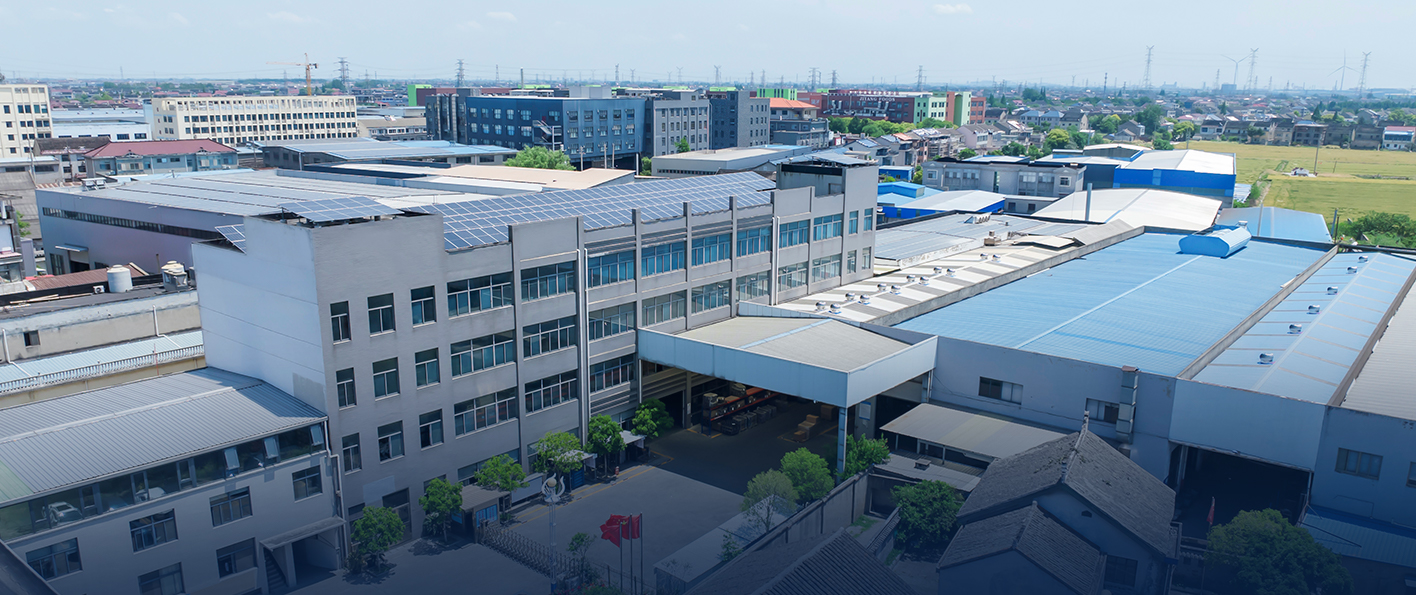
We offer full-process manufacturing capabilities from steel processing to finished product delivery, supported by stamping lines, automated welding equipment, machining facilities, and inspection instruments. Backed by an engineering team with an average of over 20 years of experience, we provide technical support from development to mass production.
With 40 years of focus on motor housing manufacturing, we have served more than 50 customers and achieved an annual production capacity of over 5 million units. Guided by quality, efficiency, and fast response, we are committed to delivering high-precision and high-reliability motor housing solutions.



