

 English
 Español
Content
- 1 What Motor Housing Deformation Actually Means
- 2 Four Stages Where Motor Housing Deformation Enters the Part
- 3 Why a Few Hundredths of a Millimetre Decide Motor Life
- 4 How Manufacturers Control Motor Housing Deformation in Steel Housings
- 5 What to Specify and Check Before Housings Reach Your Line
- 6 Frequently Asked Questions About Motor Housing Deformation
Loosen the hold-down bolts on a motor that vibrates at commissioning and slide a feeler gauge under each foot. If one foot opens by 0.05 mm or more, the frame bends every time the bolts are torqued, and the bore that carries the bearing loses roundness with it. That is motor housing deformation in its most common field form, and it is rarely the motor's own fault: the outcome was decided earlier, at the drawing press, the welding fixture and the boring machine.
This article maps where housing deformation comes from, why a few hundredths of a millimetre decide motor life, and which structural and process choices keep a steel housing round from stamping through final assembly.
What Motor Housing Deformation Actually Means
Motor housing deformation is any departure of the housing from its intended geometry, and it arrives in two forms that behave very differently once the motor is assembled.
Motor housing deformation: any measurable deviation of a motor housing from its specified geometry, including bore roundness, rabbet concentricity, flange flatness and foot coplanarity, produced by manufacturing stresses, assembly loads or service conditions.
The distinction that matters in practice is elastic versus plastic. Elastic deformation disappears when the load goes away; plastic deformation is locked in. A housing can gauge perfectly after machining and still measure out of round once a stator is pressed in, because the interference fit drives a permanent three-lobe contraction into the bore.
Elastic
Recovers when the load is released. Typical cases: soft foot bending under bolt load, clamping pressure during machining, thermal growth in service.
Hidden cost: while it lasts, it distorts the bearing outer ring and shifts the air gap.
Plastic
Permanent. Typical cases: welded-in ovality, drawn shell springback, bore contraction from an oversized stator fit.
Hidden cost: the error stays for the life of the motor and cannot be tightened away.
Four Stages Where Motor Housing Deformation Enters the Part
Deformation enters a steel housing at four points: drawing, welding, machining and assembly. Each leaves a different signature on the bore, and each has a proven countermeasure.
Deep drawing leaves residual stress, and the shell springs back oval as the material relaxes, typically 0.10 to 0.25 mm total indicator reading. Welding feet, brackets and terminal boxes adds heat and restraint; a careless sequence bows the frame or pulls the bore out of round by 0.15 to 0.40 mm. Machining contributes through cutting and clamping forces on thin walls, which is why finish stock and clamping strategy matter more than the tolerance callout. Assembly is the last entry point: the stator interference fit contracts the bore, and uneven feet bend the frame under bolt load.
| Stage | Typical signature | Typical magnitude (TIR) | First-line countermeasure |
| Deep drawing | Oval shell from springback | 0.10 to 0.25 mm | Die design and blank holder control |
| Welding | Bore ovality and frame bow | 0.15 to 0.40 mm | Symmetric sequence and rigid fixtures |
| Machining | Thin-wall deflection under clamps | 0.02 to 0.10 mm | Finish bore last, soft jaws |
| Assembly | Three-lobe bore contraction | 0.02 to 0.06 mm | Correct interference and adequate wall |
Shop floor note
Housings finish-bored after all welding consistently hold roundness several times tighter than shells bored before their feet are welded on. Sequence buys more accuracy than a tighter tolerance callout ever will.
Why a Few Hundredths of a Millimetre Decide Motor Life
Small geometry errors convert directly into electrical and mechanical losses, because the air gap is narrow and the bearing fit is precise.
A small or medium motor typically runs an air gap of 0.25 to 0.5 mm, and alignment practice keeps static air gap eccentricity near 10 percent of the gap or less. An out-of-round bore pushes the stator and rotor off center, creating unbalanced magnetic pull, vibration and noise. Mechanically, a distorted housing spreads stress unevenly around the bearing outer ring; under continuous high load the ring deforms, runs hot and fatigues early. Field repairs routinely trace bearing noise back to a bent frame or a soft foot rather than the bearing itself.
0.25-0.5 mm
Typical air gap in small and medium motors
10%
Common ceiling for static air gap eccentricity
0.05 mm
Soft foot limit before bolt load bends the frame
0.02 mm
Roundness target on a finish-bored housing
Bore roundness through the process, 120 mm bore, 1.5 mm wall
How Manufacturers Control Motor Housing Deformation in Steel Housings
Deformation control is won in three places: structure, process sequence and verification. A housing designed stiff, welded in the right order and bored last stays round; the reverse order rarely recovers.
Structure comes first, because bending stiffness climbs steeply with wall thickness. High-load frames therefore move from thin drawn shells to heavy-wall construction with a full base:
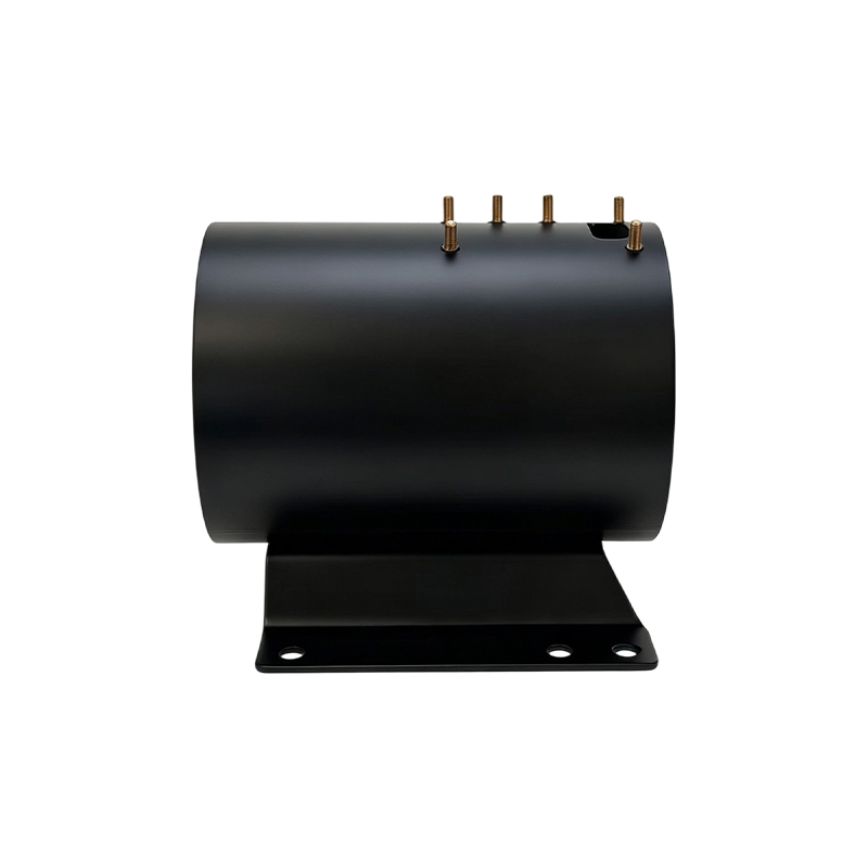
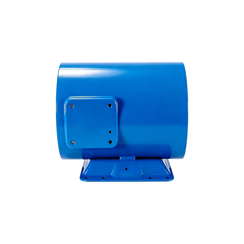 Inner Diameter 260 Heavy-Wall Motor Housing With BaseThis Heavy-Wall steel motor Housing motor housing features an inner diameter of 260mm, height of 360mm, and a material thickness of 5mm, offering extremely high compre...View Product →
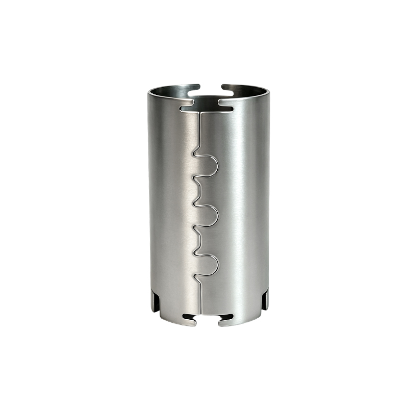
Tube-based construction takes the same idea further. A seamless steel tube blank starts round, so less correction is needed before finish boring. Our steel tube motor housing manufacturing guide for buyers walks through that route step by step, including wall selection and tolerance expectations.
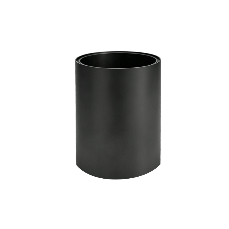 Inner Diameter 127 Heavy-Wall Motor HousingThis motor housing is precision-crafted from high-quality seamless steel tubing. With an inner diameter of 127mm and a wall thickness of 7.9mm, it delivers both precis...View Product →
Bore last, gauge round, and the rest of the process protects the geometry you already paid for.
- Weld before you bore. Finish machining comes after every thermal step, with the bore held round in a rigid fixture during welding.
- Relieve stress where it counts. Symmetric weld sequences and, on heavy sections, stress relief before the final cut.
- Clamp gently. Soft jaws and multi-point support keep thin walls from taking a set during machining.
- Gauge roundness, not just diameter. Air gauge or plug checks at several axial depths catch ovality that a two-point micrometer reads as good.
What to Specify and Check Before Housings Reach Your Line
Put geometry and measurement method into the purchase specification, then verify both at incoming inspection. Two buyers ordering the same nominal part can see very different field results depending on what the drawing actually controls.
Specify bore roundness as total indicator reading, typically 0.02 to 0.03 mm on finish-machined bores, and foot coplanarity within 0.05 mm. Name the measurement method on the drawing: air gauge or coordinate measurement at three axial depths, not a single two-point diameter check. Then run four practical checks on every batch:
- Gauge bore roundness at three axial depths and log the readings.
- Check foot coplanarity on a surface plate with the housing unloaded.
- Trial-press a stator and record the force curve; a rising spike flags bore contraction risk.
- At installation, verify each foot sits within 0.05 mm before final torque.
Mounting structure deserves equal attention, because brackets and flexible elements decide how loads path into the frame. A housing with engineered flex points absorbs mounting stress instead of passing it into the bore:
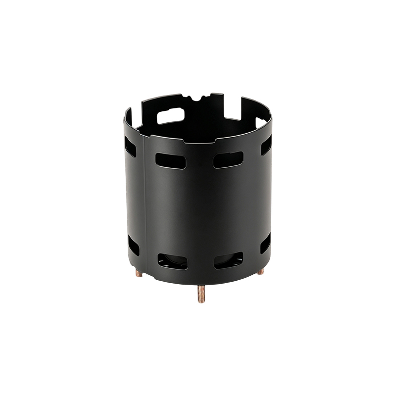
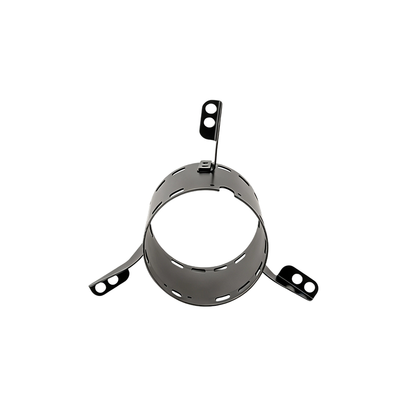 Inner Diameter 120 Steel Motor Housing With Three Flexible BracketsThis steel motor housing features a precision-engineered structure with an inner diameter of 120mm, height of 105mm, and a wall thickness of 1.5mm, achieving compact l...View Product →
Where several structures are in play, compare wall, base and bracket options across the standard steel motor housing range before locking the drawing.
Treat roundness as a process outcome, not a drawing wish. At Jiangsu Yufeng Electric Co., Ltd., stamping, welding, machining and inspection run in one plant, which is what makes sequence control enforceable and keeps deformation risk out of your line.
Frequently Asked Questions About Motor Housing Deformation
Can a deformed motor housing be repaired?
Elastic causes can: shimming the feet and re-torquing in sequence usually removes soft foot distortion. Plastic deformation of the bore generally calls for re-machining or replacement, because a bore that is more than a few hundredths of a millimetre out of round will keep working the bearing outer ring for the rest of the motor's life.
Does a thicker wall always stop deformation?
Thickness helps a great deal, since bending stiffness scales with roughly the cube of wall thickness, but it does not excuse poor practice. A thick housing welded in the wrong order or clamped carelessly can still arrive out of round. Heavy-wall and tube-based construction deliver their full benefit only when paired with weld sequencing and finish boring last.
Is deformation always the housing maker's fault?
No. Installation soft foot, over-torqued mounting bolts, pipe strain and thermal cycling all deform housings that left the factory in specification. That is why soft foot checks belong in the installation procedure and why incoming roundness checks matter on both sides.
Which construction resists deformation best?
For high-load and larger frames, heavy-wall steel and tube-based housings hold geometry best, and 304 stainless versions bring the same stiffness where corrosion resistance is also required. Match the structure to the load path rather than buying thickness alone.
 Previous