

 English
 Español
Content
- 1 What Motor Housing Continuous Stamping Actually Involves
- 2 Tolerances and Size Windows You Can Realistically Hold
- 3 Where Motor Housing Continuous Stamping Wins and Where It Does Not
- 4 The Five Defects That Scrap Housings and How Lines Fight Back
- 5 How to Qualify a Continuous Stamping Housing Supplier
- 6 Frequently Asked Questions
A drawn steel shell with a 140 mm inner diameter can leave a press line every few seconds, and that pace is the whole reason appliance and industrial motor makers specify motor housing continuous stamping for their highest-volume programs. Instead of moving blanks between standalone presses, a continuous line feeds coiled strip through a multi-station progressive die, where blanking, drawing, redrawing, piercing and trimming run as one coordinated sequence. For a purchasing team, that choice decides cost per part, delivery reliability, and whether the ten-thousandth housing measures the same as the first one off the tool.
What Motor Housing Continuous Stamping Actually Involves
Continuous stamping is a choreography problem before it is a force problem. The press supplies the tonnage, but the strip layout, the feed system and the die stations decide whether a housing comes out round, straight and repeatable at speed. Each station performs one operation, and the carrier strip ties them together so nothing drifts between hits.
On a typical housing job, the stations break down like this:
Tolerances and Size Windows You Can Realistically Hold
A well-maintained progressive line holds inner diameter variation to a few hundredths of a millimetre when a sizing or ironing station is built into the die, and machined bearing seats can tighten critical dimensions further. What buyers should check first, though, is not a tolerance table but the size window, because the forming route sets the limits before any tooling is cut.
Deep drawing from sheet covers small and mid shells economically, which is why most appliance and industrial drive programs sit in that window. Heavier walls and larger diameters move toward tube or fabricated construction. For a wider framing of the buying decision, our steel motor housing guide walks through the full selection logic.
| Manufacturing route | Typical ID window | Wall and structure | Best fit |
| Drawn steel shell on a progressive line | 29.6 to 160 mm | Sheet wall; bases, brackets or flexible elements welded on | Appliance and industrial drive motors |
| 304 stainless drawn shell | 139 to 180 mm | Corrosion-resistant sheet wall | Washdown, food and outdoor equipment |
| Heavy-wall steel shell with base | 260 to 343 mm | Thick wall with welded base | Large industrial and special equipment |
| Steel tube housing | 113 to 127 mm | Thick wall produced from tube | High-load and special equipment |
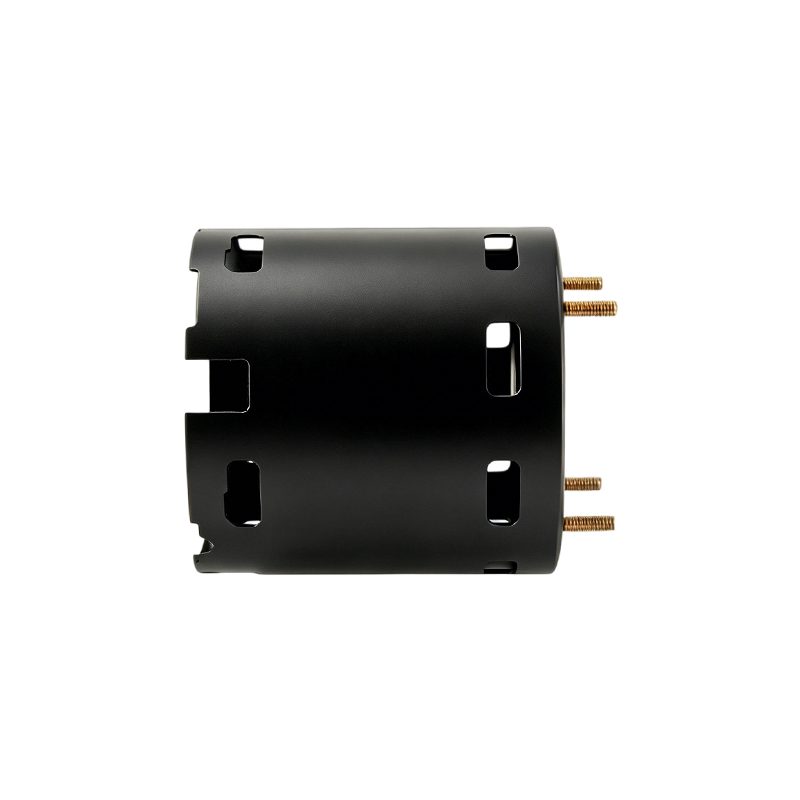 ID 82.4mm Thin-Wall Steel Motor Housing with Welded End CoversA 1.0mm-wall drawn steel shell with welded end covers, integral bearing seats, and axial venting for cooling. It suits the article's small-to-mid drawn shell window for handheld, lightweight motor applications.View Product →
Where Motor Housing Continuous Stamping Wins and Where It Does Not
Continuous stamping wins on volume, repeatability and cost per part, and it loses on flexibility and very thick walls. Pick the wrong route and the symptoms are predictable: tooling that never reaches break-even, or walls that tear no matter how the blank holder is tuned.
- Annual volume runs into six figures and the design is stable across model years.
- The shell inner diameter sits inside the drawn-shell window of roughly 29.6 to 160 mm.
- Cost per part and lot-to-lot consistency outrank the tooling budget.
- Brackets, bases and machined seats will be finished in house after stamping.
- Volumes are low or the geometry is still moving between revisions.
- Walls are heavy and diameters run large, past what deep drawing handles well.
- The profile matches tube construction better than sheet.
- Prototype speed matters more than unit cost on the first orders.
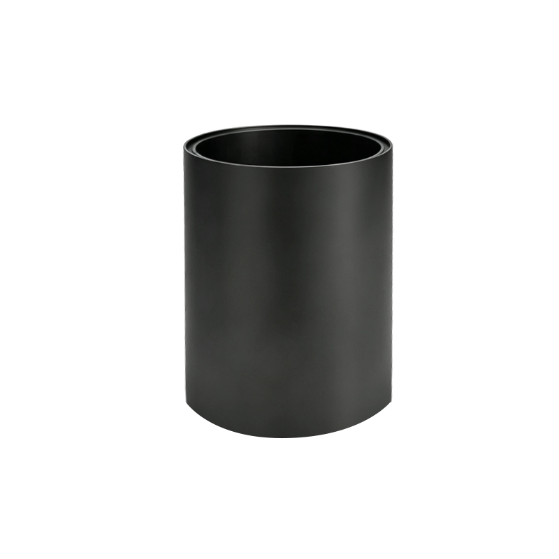 ID 127mm Heavy-Wall Seamless Steel Motor HousingMachined from seamless steel tubing with a 7.9mm wall, this housing handles high torque and vibration where drawn sheet cannot. A fitting example for the article's point about heavy-wall construction beyond deep drawing limits.View Product →
The Five Defects That Scrap Housings and How Lines Fight Back
Almost every scrap-cause review on a housing line ends at the same five suspects, and all of them are controlled at the die and feed level rather than caught at final inspection.
- Flange wrinkling: blank holder pressure and draw bead geometry hold the flange flat; once wrinkles iron into the wall, the shell is scrap.
- Tearing at the punch radius: the drawing ratio is too aggressive for the material, so the fix is another redraw station or a softer radius.
- Earing on the rim: sheet anisotropy raises ears at fixed angles, so the die plan adds trimming allowance and the rim cleans up.
- Springback and ovality after trimming: die geometry is compensated and a final sizing station restores roundness on the inner diameter.
- Coating flaking on galvanized strip: tight feed bends and die friction chip the zinc layer, so feed radius and lubrication are controlled.
When wall thickness climbs past what drawing handles comfortably, the honest answer is to change routes rather than force the sheet; our steel tube motor housing manufacturing guide covers that path in detail.
How to Qualify a Continuous Stamping Housing Supplier
Judge the process chain, not the unit price. A supplier that outsources the die or the machining hands the most critical variables to someone you cannot audit, and the price gap usually reappears as freight, lead time and tolerance problems.
- In-house die engineering: ask who designs, cuts and repairs the progressive die, and how fast a worn station can be rebuilt.
- Press and feed capability: tonnage, bed size and the servo feed system decide which shell sizes can run at rate.
- A complete secondary chain: welding of bases and brackets, machining of end faces and bearing seats, and surface treatment under one roof remove handoffs that stack tolerance.
- Inspection behind the press: roundness, wall thickness and material certification checked with proper instruments, not just calipers.
- Volume evidence: real capacity, years in the process and a verifiable customer base.
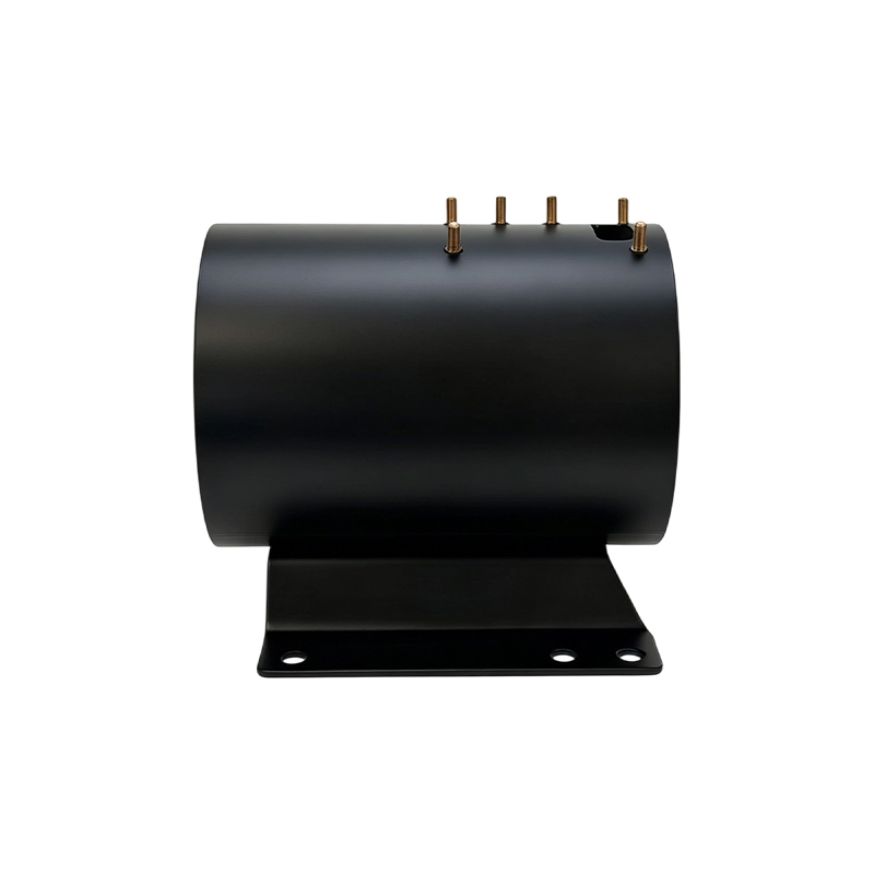
Our own plant runs stamping, automatic welding, machining and surface treatment in one flow. Jiangsu Yufeng Electric Co., Ltd. has focused on motor housing manufacturing for 40 years, supports customer programs with an engineering team averaging more than 20 years of experience, and ships more than five million housings a year to over 50 motor manufacturers. Shells like our 140 mm housing with two welded brackets show how stamping and secondary welding combine into a single deliverable.
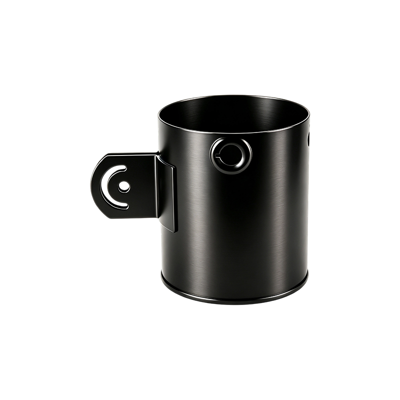 ID 140mm Steel Motor Housing with Two Welded BracketsA drawn steel shell with phosphated powder-coated finish, sealed cable gland threads, and two welded mounting brackets. It illustrates the article's point on combining stamping and secondary welding into one deliverable.View Product →
Frequently Asked Questions
What size range fits motor housing continuous stamping?
Drawn sheet shells run from about 29.6 mm up to 160 mm inner diameter on our lines. Above that, wall thickness and press tonnage push the job toward heavy-wall or tube construction, which we produce in inner diameters up to 343 mm.
How is continuous stamping different from transfer die stamping?
In continuous stamping, the strip carries the part through every station inside one die. In transfer stamping, individual parts are moved between separate dies by fingers or robots. Continuous lines run faster per part; transfer lines handle deeper draws and larger shells.
Which materials work best for stamped housings?
Cold-rolled steel is the default for appliance and industrial shells. 304 stainless suits washdown and corrosive environments, and galvanized strip runs well when feed radius and lubrication are managed to protect the coating.
What tolerance should I expect on the inner diameter?
With sizing or ironing built into the progressive die, expect inner diameter control within a few hundredths of a millimetre. Where a motor design needs more, machining after stamping sets bearing seats and end faces to final dimensions.
 Previous