

 English
 Español
Content
- 1 Motor Housing Design Trends: From Universal Shells to Application-Specific Mounting
- 2 Motor Housing Design Trends: Thermal Management Becomes a Housing Task
- 3 Corrosion Resistance Moves into Material Selection
- 4 Automated Assembly Lines Set New Motor Housing Design Trends
- 5 What These Motor Housing Trends Mean for Motor Procurement
- 6 Frequently Asked Questions
When a motor housing drawing crosses an engineer's desk in 2026, it rarely looks like the plain cylinder shown in older catalogs. The revision list often names three things: a bracket pattern that matches a robotic assembly cell, a cooling-channel pocket where a straight bore used to be, and a tolerance that forces a machining center instead of a lathe. These demands are not isolated cases. They come from motor housing design trends that have moved from EV programs into industrial drives, household appliances, and special equipment.
For a manufacturer such as Jiangsu Yufeng Electric Co., Ltd., which supplies steel and stainless steel housings from 29.6 mm to 343 mm internal diameter, these trends decide which drawings get quoted and which tooling gets built. The sections below break down the four trends most likely to appear in a new motor program.
Motor Housing Design Trends: From Universal Shells to Application-Specific Mounting
The clearest motor housing design trend is the end of the universal shell: housings are now tooled for one mounting layout instead of being cut from a generic tube.
Designers are specifying bracket-mounted frames for pumps and blowers, foot-mounted shells for gear reducers and compressors, and flange combinations with a pilot register for face-mounted motors. This shift moves manufacturing scope upstream. The housing supplier can no longer ship a plain tube; it must machine bracket faces, drill dowel holes, and validate foot flatness against the customer's interface drawing. As a result, bracket-mounted motor frames and foot-mounted shells have become separate product families rather than options on a generic line.
One practical example is a 140 mm housing for a pump drive that carries two machined brackets. The pitch between brackets, the face height, and the parallelism are checked on a CMM before the first sample leaves the factory.
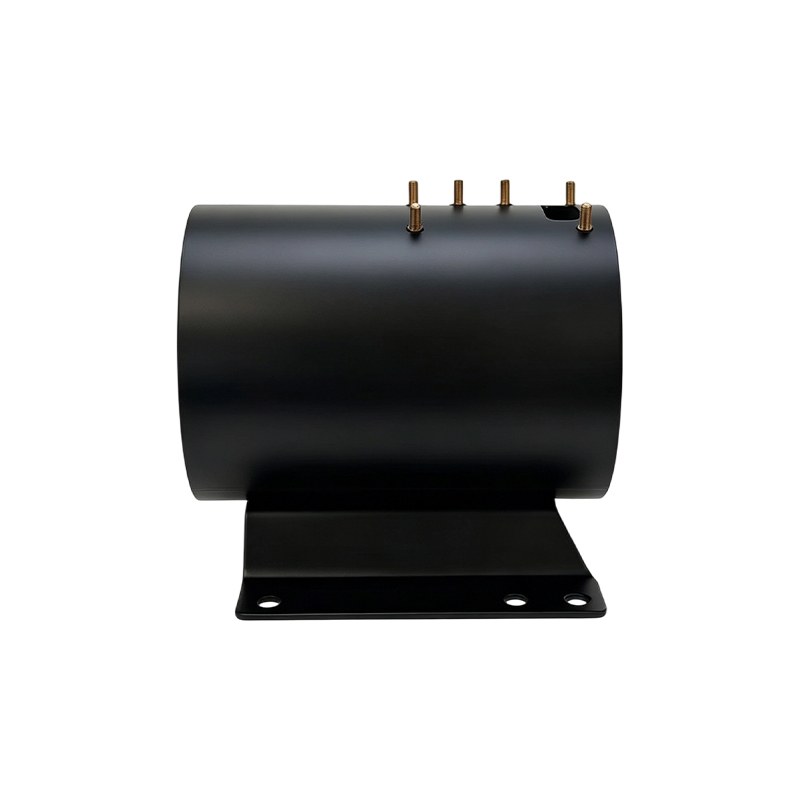
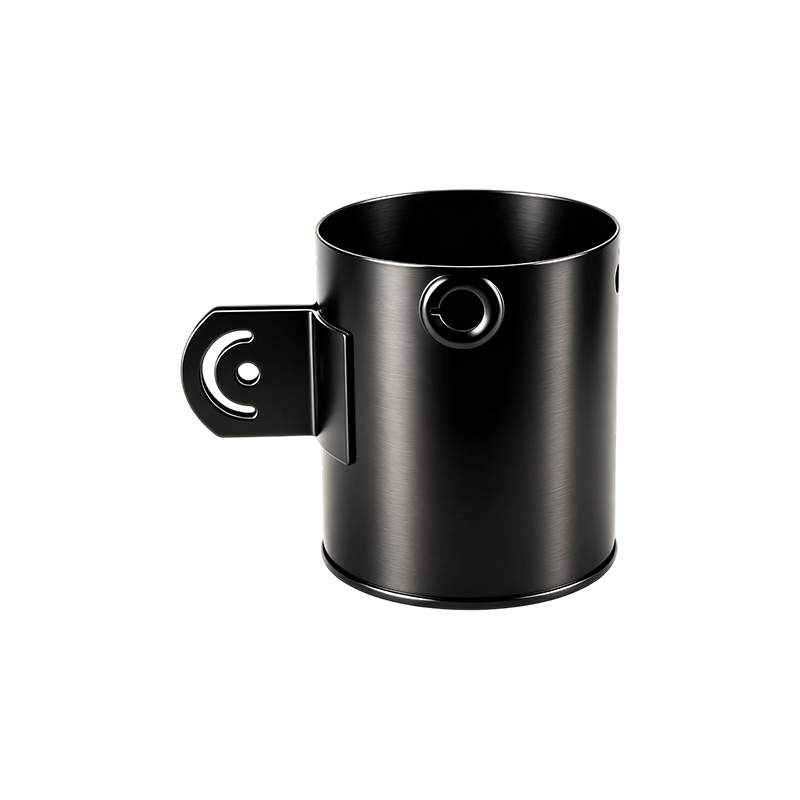 Steel Motor Housing with Two Welded Brackets for Pump DrivesThis 140 mm inner diameter housing with two welded mounting brackets is machined after welding to maintain pitch, parallelism, and face height, ensuring reliable fixation for pump drive units.View Product →
When brackets are welded, heat input can pull the machined faces out of parallel. A supplier that machines after welding, rather than before, holds those tolerances reliably across a batch.
Common mounting patterns to evaluate
- Side-face bracket mounting with tapped or through holes for compact pump and blower motors
- Flat-base foot mounting with slotted holes for vibration pads and rail systems
- Flange mounting with a pilot register and bolt circle for face-mounted motor assemblies
The measurable outcome: a housing with machined bracket faces can cut motor assembly shimming time from minutes to seconds while removing one source of rotor-to-load misalignment from the process.
Motor Housing Design Trends: Thermal Management Becomes a Housing Task
Thermal management is the fastest-changing motor housing design trend because the housing is now drafted as a heat exchanger, not a protective cover.
As motors shrink for the same output, the housing must remove more heat per square centimeter of surface. This rewrites the geometry in three ways: deeper fins, integrated cooling jackets, and air passages machined into the wall. In steel housings, the material's thermal conductivity cannot compete with aluminum, so designers compensate with surface area and airflow control. The chart below shows why fin geometry matters.
Carbon steel conducts heat at about 50 W/(mK), roughly one quarter of aluminum's 205 W/(mK). Stainless steel drops to 16. A steel housing with tall fins and a directed fan flow can still meet thermal targets, especially in indoor industrial settings where impact resistance and cost weigh more than weight.
Another underrated issue is uniformity. A housing with asymmetric fins or a single axial air passage creates a hot spot on the opposite side, which shortens winding insulation life. The direct answer for buyers: ask for a thermal simulation report before first article, not after.
Corrosion Resistance Moves into Material Selection
Corrosion resistance is now a material-selection decision in motor housing design, not a paint-shop afterthought.
Food processing, chemical pumps, coastal HVAC, and certain EV under-hood locations specify stainless steel housings because edge corrosion at painted cutouts and bolt holes appears within months in those environments. Grade 304 is the baseline; grade 316 is reserved for chloride-heavy applications, though it is less common in housings because of machining cost.
Welding stainless housings demands controlled heat input. A 139 mm 304SS housing rolled from sheet must hold its bore roundness after weld shrinkage; fixtures and a defined weld sequence keep the inside diameter within tolerance.
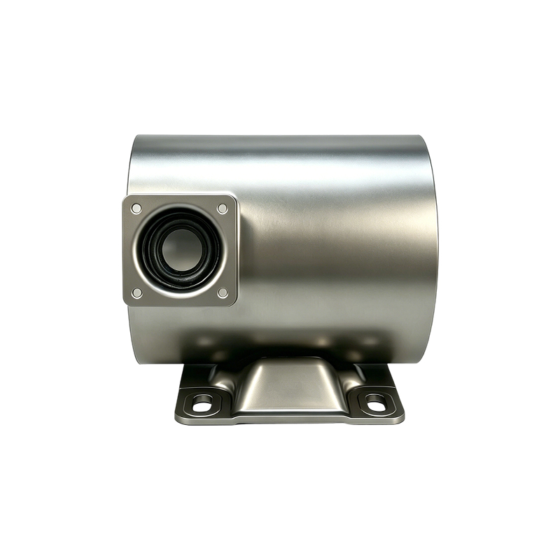
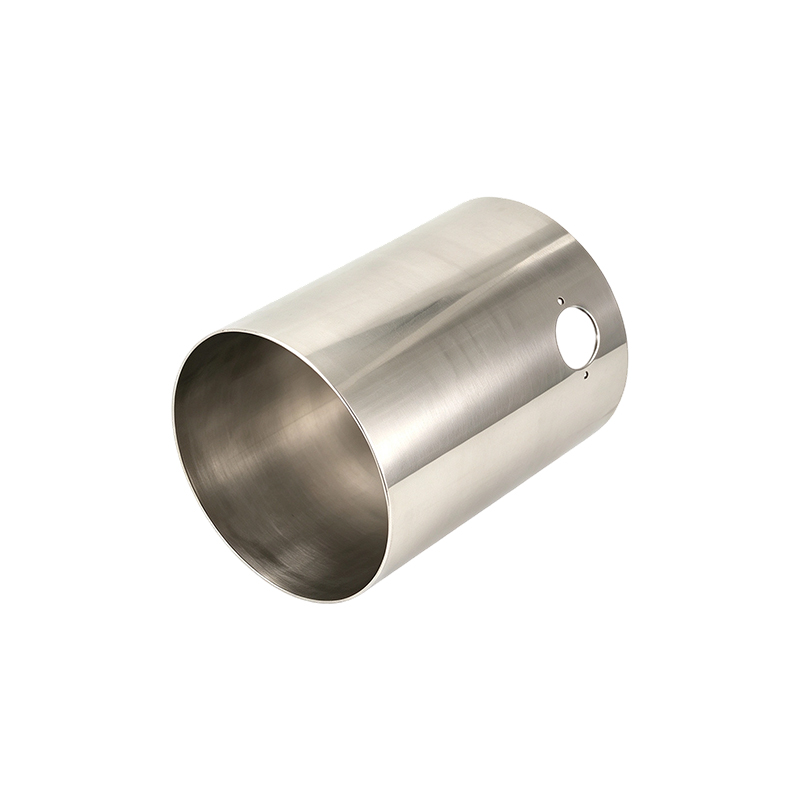 Welded 304SS Motor Housing with Controlled Heat InputThis 139 mm stainless steel housing must preserve bore roundness after welding; controlled heat input and fixtures are essential, and specifying salt spray acceptance criteria in drawings prevents field failures.View Product →
Designers should write the corrosion acceptance standard into the drawing, such as salt spray hours or humidity exposure duration. Without that, suppliers will default to cosmetic passivation, and the housing may fail in the field at painted edges.
Automated Assembly Lines Set New Motor Housing Design Trends
Automated press-fit and staking lines are setting new motor housing design trends by demanding repeatable bore geometry at scale.
When a rotor is pressed into a housing, bore tolerance determines whether the press stops at the correct force or rejects the sub-assembly. Common requirements for small laminated motors now include bore roundness within 0.03 mm and face squareness within 0.05 mm. For a 2.0 mm stamped steel housing, that precision is achieved through process choice: a precision boring bar, air gauging, and statistical process control.
Larger housings shift the challenge to fixturing. A 260 mm ID heavy-wall steel housing with a base keeps its geometry only if the base is clamped before boring and released after the part reaches room temperature.
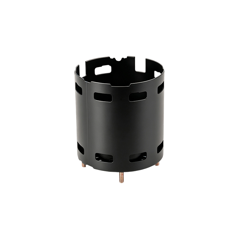
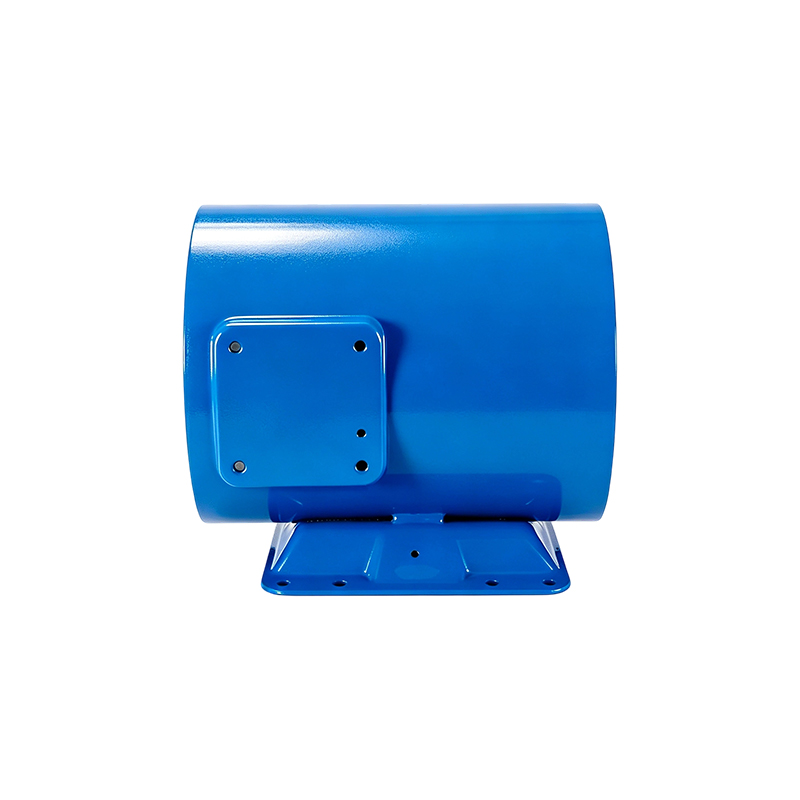 Heavy-Wall Motor Housing with Base for High-Power ApplicationsWith 260 mm bore and 5 mm wall thickness, this housing resists torque and impact. Proper clamping before boring and verification of bore circularity and base flatness are critical for automated assembly.View Product →
Weld fixtures also protect the housing during tack welding; a good fixture can be the difference between a 0.05 mm round bore and a 0.12 mm oval after cooling. Buyers should request a dimensional verification report that separates bore circularity, bracket face parallelism, and base flatness. A single "diameter OK" line is no longer enough for automated assembly.
What These Motor Housing Trends Mean for Motor Procurement
For motor manufacturers, motor housing design trends change the questions asked at the RFQ stage, not just the drawing.
The supplier's process capability matters more than the catalog page. A housing with integrated mounting and thermal features carries process risk that a plain cylinder never had. That is where an in-house chain of stamping, welding, machining, and surface treatment pays off: fewer handoffs, faster fixture iterations, and shorter reaction time.
| Trend | What changed | Procurement action |
| Integrated mounting | Brackets and feet machined to a fixture drawing | Send the fixture drawing with the RFQ |
| Thermal architecture | Fins and cooling channels become part of the housing | Review the thermal simulation report before first article |
| Stainless material | Welding and machining cost increases | Define salt spray hours and material grade |
| Tighter tolerances | Roundness and parallelism controlled at scale | Require SPC data with PPAP |
Three requests that separate informed buyers
- Ask for the machining sequence, including how the housing is clamped during boring.
- Ask for the first-article report with CMM data at the stated tolerance.
- Ask for salt spray or humidity test results before production tooling is cut.
Frequently Asked Questions
What is a motor housing?
A motor housing is the structural shell that supports the stator and rotor assembly, protects internal components, transfers heat to the surrounding air, and provides the mounting interfaces for the driven machine.
Which material is best for a motor housing?
Carbon steel is the default for most industrial motors because of stiffness, weldability, and cost. Stainless steel becomes the right choice when corrosion resistance is required, and aluminum suits applications where weight and thermal conductivity outweigh material cost.
What tolerance is standard for a motor housing bore?
For small to medium motors, bore roundness of 0.03 to 0.05 mm and a bore diameter within H7 are common in current design reviews. Larger heavy-wall housings often work with 0.05 to 0.08 mm, depending on the press-fit assembly process.
How do motor housing design trends affect lead times?
Integrated mounting features and thermal validation add machining and inspection steps, so a trend-driven housing typically takes longer than a plain tube. A housing manufacturer that controls stamping, welding, and machining internally can keep most of that increase inside the tooling and first-article phase.
 Previous